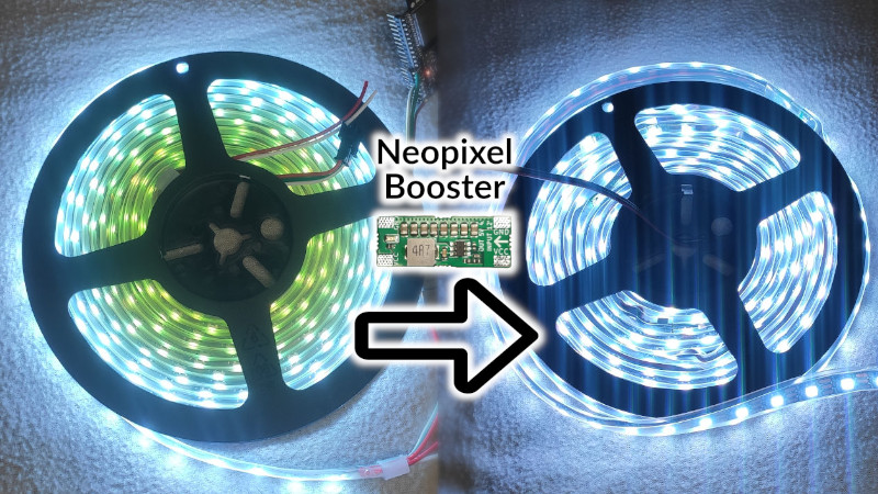
Addressable LED strips, most commonly using the WS2812B, have revolutionized the pursuit of the glowiest and flashiest of builds. No longer does a maker have to compromise on full RGB color or number of LEDs due to the limitations of their chosen microcontroller, or fuss around with multiplexing schemes. However, the long strips of bright LEDs do have an issue with voltage drop on long runs, leading to dimming and color irregularities. Thankfully, [Jan Mrázek] has come up with a useful solution in the form of the Neopixel Booster.
The device consists of a small PCB which packs a 5 volt regulator capable of putting out up to 4 amps. It’s designed with pads that match typical Neopixel strips, such that it can be neatly soldered in every 50cm or every 60 LEDs or so. Each booster PCB is fed with a set of fat power wires, at between 6-18 volts. This allows electricity to be fed to the full length of the strip at higher voltage, and thus lower current, greatly reducing resistive power losses. By having several regulators along the length of the strip, it helps guarantee that the whole length of a long run is receiving plenty of voltage and current and can light up the correct color as desired.
It’s a well thought out solution to a frustrating problem, and [Jan’s] efforts on the design front mean that a 5 meter long waterproof strip can be converted in around about an hour. We can imagine this could be manufactured into strips in future, too. If you’re wondering what to do with all those LEDs, consider making yourself a custom display.


There were strips available on aliexpress with a similar board soldered inline every meter or so years ago. Nothing new.
link?
>”a suitable wire for 21 A will be pretty thick (around 3.5 mm²)”
But note: you only need such cabling for the power input to the strip. You don’t need 21 amps all the way to the end of it. If you’re clever about it, you can feed the strip from both ends, which also halves the cabling cross-section area. I don’t think it requires any unreasonably hefty wires to make it work entirely without these boosters.
True indeed. That’s a little overestimate. But once you start chaining multiple strips it becomes relevant. And it is actually pretty convinient to power all the strips from the starting point (i.e., your power wires are part of the LED strip).
Yep. This is what I did. Took me a lot less than an hour to run a pair of medium-ass wires alongside the strip and tack them onto the power rails every few feet.
Exactly what I did this Christmas with about five sets in series. Worked great and everything powered from the source. Kinda wish the strips had this designed into them…i.e. a nice beefy pair of bus wires that paralleled the LEDs. Would make for a clean installation.
Design a regulator that accepts up to 48 volts and then that wire size can get pretty small. A 48V feed would only require 1/8 the wire size for 2.6 Amps. Buck regulators are available for less than $2.00 that will handle an input range of 7V to 48V.
Those regulators will need to dissipate a lot of heat. It might not be a good idea for that size.
Um, he explicitly stated “buck regulators”
Your complaint is only valid for linear regulators.
even buck regulators have losses. especially when they’re $2 and tiny.
i think we’re talking about regulators outputting 20W. even one 90% efficient is going to warm up. probably needs to be <25C/W to ambient in order to stay a reasonable temperature. (2.22W waste heat, "reasonable"==80C(!!!), so a <55C rise given 2.22W.)
if you know of a product which will accomplish Tom's specs while staying "cool", i'd very much like to hear about it.
See https://roboticsbrno.github.io/RB0004-NeopixelBooster/eval_v2/index.html
Even this design with efficiency >90% gets to 50°C under 4 A load.
It’s still just #10 thhn. Might want to look at voltage dop after the driver. Bigger wire will have less. If it is a longer run from the driver to the light strip, might want bigger wire to combat this.
I was really hoping that it would just be a boost converter to take the 4.2v droopy signal out the end of one strip and boost it up to 5.0v into the next strip. Really push those traces to their limits!
Well, when it woud be a boost converter using the original line, wouldn’t it mean it draws more current from the 5V line, thus leading to a larger current draw, thus having a bigger voltage drop, thus drawing more current… ?
Please do a little math: Even with 100% efficiency, that 4.2V to 5V conversion will increase the current draw from the prior strip by nearly 20% for each following boost converter, etc. Much better to run two more wires.
But not as exciting!
See F-Amp for data signal boosting across long distances:
https://www.pixelcontroller.com/store/index.php?id_product=53&controller=product
Don’t forget to add a 400ohm resistor right before the 1st led after a long data wire distance.
I have been ruminating on this for a while. I like this solution lots. It is the product I was flipping through google , amazon, aliexpress, and bangood looking for last October deciding whether I needed to run outlets every 20 feet under the brim of my roof. Using a moderate voltage (but still low) solution allows me to space out my outlets better and reduce my wiring expense fairly dramatically. Jan, thanks for putting in the time to make a thoughtful product.
I always wondered why these LED strips don’t have power regulators every meter or so and a 12V rail supply. Heat dissipation shouldn’t be the problem and you can cut the strip every 10cm behind a converter (it just shortens the length of the 5V rail).
There is a simpler solution to avoid this problem: cross-feeding the strip.
If you power an arbitrary long strip of LED on one side with ground and signal, and on the other end with the +, each led along the strip will be fed with exactly the same length of conductor overall, assuming that both sides (+ and -) have the same specific resistance (ohm/m), the voltage at the LED pins will be the same all along the strip: no fade out or color change at all along the strip.
With a standard constant voltage power supply, there will be a drop at the LED pins, depending on the current drawn by the whole strip, but it will be the same for all the LEDs along the strip. If the supply has an external feedback to measure the voltage at one strip end, it will compensate instantly.
If you can’t find the right power supply with external feedback and can’t live with the power drop when lots of leds are in use, take an unregulated power supply with a sufficient voltage (~7.5 V) and a $1.50 LM338 and a pair of resistors for each slice of 5A you need to supply. It will produce some heat but it works.
Thanks
This looks really good.
I’ve been using the KNT 5A 5v UBECs for this purpose for a while.
They are designed for use with R/C models, but the small size and sturdy construction works really well for lots of things.
I think it is cheaper to buy a WS2815 12V strip…
Also doesnt need a lot of time soldering PCB’s in between
You are right. There is log on the project about the (theoretical) comparison: https://hackaday.io/project/176744-rb0004-neopixelbooster/log/188029-how-does-this-compare-to-ws2815
Might make sense when you power your LEDs from battery.
Bang on. Replaced my 5m strip (300pm) last year with the 2815 strip. Pretty much a drop in replacement too. Even with a drop in 5v in 4 spots it still browned once white was on about 75% brightness (probably terrible traces in the strip). This one has one 12v source and doesnt brown at all over the whole strip on 100%.
Back in 2009, the Armani store on 5th Avenue in New York had a 3 story tall video façade made up of aluminum extruded beams, with 1.5 watt RGB LEDs spaced at 100mm apart. All of the beams had wire entry from the top only where the beam hung from a 1/4″ threaded rod.
To solve this same issue of daisy chained LED PCBAs, there were 2 sets of wire harnesses that also ran down the beam. This allowed direct power feeds to the lower half. Data only ran through the boards, so the harness was only 2 wires. They ran off of 24V and with all LEDs at full white, a 5 segment beam for 3 floor height would pull 6.5 amps. If you look at one of the photos of the store from back then, you can see a lot of current in use. I worked for the CM that built the PCBAs and beams for the sub that worked with Martin, who was the product design sub for SaMa who designed the setup for Armani. Lots of cooks in that kitchen…..
https://www.martin.com/en/news/armani-5th-avenue-new-york-usa
Thanks for the inspiration.
Is this only a sales promotion?
WTH.
Regardless of the technical description. It does not interst me that much.
As a reader of a hacking blog I want to make it easily by myself.
So , if You the creator, do not publish at least the schematics go away.
look for another place to put your advertising.
Did you at least looked into the documentation before writing the comment? Or on the hackaday.io project? There are the full sources! See: https://github.com/RoboticsBrno/RB0004-NeopixelBooster
I don’t agree with the way [Peter_s] commented, but his interest in a schematic isn’t unreasonable. I only see the schematic in the github which is only linked at the very bottom of the Tindie which otherwise contains only the same content as the hackaday.io page. I don’t blame [Peter_s] for not finding it.
Thank you for your (reasonable) response; I put the GitHub repository into the material/sources/documentation on Hackday.io and I always try to link Hackaday.io. I din’t feel the need to promote the link more – I expect everyone interested is aware of this section. Nearly every project on Hackday.io has it. And I actually see the need to give the introduction what it is and what it does. As you can see from my GitHub, my projects are open and available, so I consider the “being-open” normal and nothing that needs promotion.
I’ve never used hackaday.io to document a project, so maybe that’s where I fall down with knowing where to look in it to find things. I’ve seen projects documented in all kinds of different ways using it as well. I should take the time to make something and document it here, I’m sure I’ll learn something.
TLDR >5V secondary power rail with 5V buck converters tapping into the strip every so often
And remember that if you need a clock line the APA102c LED package is an excellent option. Probably better for displays.
Trades wire gauge for complexity.
If you’re doing this, mayn’t you just as well make it USB-C or PoE compatible???
PoE is usually weak for LEDs so there’s no point there. Actually, I am working on USB-C QuickCharge & Power Delivery frontend. But it will take at least a few months to finish. But first project logs coud be out much sooner!
That’s like saying batteries are weak because AAA batteries are weak, the weak end of PoE is 10W, the spec goes up to 100W intermittent 71W sustained now.
You are right; I should have formulate my answer more precisely; what I meant is that the usual solutions for PoEs are weak for such an application. Most of the consumer-grade routers and adpaters are usually 10-15W rated. Higher power adapter exists, however, are much more expensive thus not sure if they strike the maker community. Thus, I think there will be not much users and definitely, I wouldn’t be a user for such a solution/product. Thus It makes no sense to invest in such solution.
Fair enough, understandable.
The title photo shows a couple reels of LEDs lit up.
Please do not leave reels powered up like that, the heat build up will damage the LED strips.
DAMHIKT
But they are so nice on photos! It tells much more than a weird bunch of cables.
PS: First the reel melts, then LEDs. I did the experiment for you many, many years ago!
Yeah, experiment. I’ve dont this… experiment… too.
Seriously? I thought it was a fire hazard but not all that likely.
LED strips should have embedded temperature and voltage diagnostics, and run natively from 24v with this kind of power board embedded!
Should, but did you buy the cheapest one you could find? :-D
It probably depends what your ambient temperature is. Either way It does suffice for a quick demonstration.
I did not intend to be critical of the photo,
I just wanted to save new users of LED strips the damage to their strips.
Am I the only one thinking this is completely useless? If you power inject at both ends of the LED strip you should be fine. Or at worst you can solder wires directly to the pads on the strip in the middle if you’re still having ban issue with voltage drop. My whole time playing with LED strips as long as your putting power/ ground at both ends of a strip you’re fine. Even with power hungry Apa102 5v strips
The use case for me, as an author was:
– it allows you to use thin wires attached directly to the strip, thus your strips remain flexible and not bulky.
– chaning 20 meters of LEDs strip (you don’t have to worry about separe power wires)
– when you want to power your LEDs with higher voltage power supply or Li-ion accumulators.
Yes, it is basically what you suggest – put extra wire and tap on the ends and in the middle. But it has a nice small form factor, it is easy to solder and allows you to use higher voltage, thus thinner wires.
Fair enough I guess I had overlooked the positives of using thinner wires but you still need to run wires to the boards that are still placed every 4-5 meters right? So with it you’re still running meters of wires to the board and then to the strip vs just running slightly thicker wires to the strips
What us the point if you have to supply power t
o each module you may as well apply power directly to the led string at suitable intervals
The point is made in the linked article, but basically:
V = IR
and:
P = IV
hence:
P = I²R
So if you want to carry a lot of power, and you don’t change voltage, current becomes a limit. So you’d have to change resistance, but in order to do that you need thicker power cables.
What these modules let you do instead is supply a higher voltage, so that current isn’t limited, and you can use thin power cables. It’s literally the same concept as an electrical grid distributing power at hundreds of thousands of volts but stepping it down for use in homes.