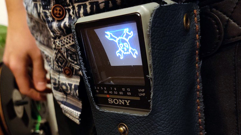
From the perspective of a later decade it’s sometimes quaint and amusing to look back at the technological objects of desire from times past. In the 1980s for example a handheld television was the pinnacle of achievement, in a decade during which the Walkman had edged out the transistor radio as the pocket gadget of choice it seemed that visual entertainment would surely follow. Multiple manufacturers joined the range of pocket TVs on offer, and Sony’s take on the format used a flattened CRT with an angled phosphor screen viewed from behind through its glass envelope. [Niklas Fauth] took one of these Sony Watchman devices and replaced its TV circuit board with one that turned it into a vector display. The Sony Scopeman was born!
The schematic is deceptively simple, with an ESP32 receiving audio via Bluetooth and driving the deflection coils through a pair of op-amps and a set of driver transistors. These circuits are tricky to get right though, and in this he acknowledged his inspiration. Meanwhile the software has two selectable functions: a fairly traditional X-Y vector ‘scope display and a Lorenz attractor algorithm. And of course, it can also display a vector version of our Wrencher logo.
We like the Scopeman, in fact we like it a lot. There may be some discomfort for the retro tech purist in that it relies on butchering a vintage Watchman for its operation, but we’d temper that with the observation that the demise of analogue broadcast TV has rendered a Watchman useless, and also with the prospect that a dead one could be used for a conversion project.
[Niklas] has had more than one project appear on these pages, a memorable example being his PCB Tesla coil.


Für Hackaday reicht’s.
🤡
My big question is… How did it manage the difference in deflection needed when painting the lower scalines versus the upper ones? Was 100% electronics, or the tube/deflection coils had a design that achieved that automagically and the electronics didn’t have to know if it was a top or bottom line what was being painted?
mirror is convex
It was electronics. I used one of these in a little computer back in the 90s, and the horizontal sweep was driven harder at the bottom than at the top. As for the electronics having to know if it was a top or bottom line, no problem there because the H and V sweep were generated by the same chip. This turned out to be problematic because that chip (at least in the particular model I had) demanded strict NTSC timing, meaning it had to have 525 lines, interlaced. If you tried to give it 524 or 526 lines without interlace, it would drift and re-sync, drift and re-sync, every few seconds. I had to redesign my whole display counter section. As a bonus though, I ended up with twice the resolution I originally intended!
Oh – one more thing: the phosphor screen was curved in such a way (concave cylindrical section from top to bottom), that the horizontal sweep amplitude increased linearly from the top to the bottom, simplifying the electronics. So there was just a bit of geometric magic there.
Where this tube failed in my view was that because there was no magnetic shielding (couldn’t be, since that would block the screen), the raster moved significantly as you rotated it, just from the Earth’s magnetic field. Not a big deal with an overscanned TV picture, but kind of big if you cared about all of the image.
I should add here, since this project is a vector display, it has to vary the horizontal gain with the vertical position of the beam. Not exactly sure how that was handled.
That detail about the geometry is exactly what I was asking for. Thanks!!!!!
Good question – I’d also like to know. Normally current in one direction in the vertical deflection coil means deflection above centre. Zero current means on the centre (centre line if there’s horizontal scanning going on). Current in the other direction means deflection below centre. So a double ended circuit is needed (positive and negative current, like in a loudspeaker).
Not sure if the Sony tube used here has equal division above and below (like normal CRTs), or if it has some offset so it only needs current in one direction or something. Would love to know (having designed a CRT circuit myself, although could never get the horizontal circuit to work with the 2N3055 I had, being a poor student at the time)
In the original circuit the supply voltage of the horizontal deflection has a signal component from the vertical deflection superimposed, it’s called keystone correction. There is also some “dynamic focus”, where the focus voltage is modulated by a part of the vertical deflection voltage.
I’m waiting for someone butchering one to do that C64 portable we saw renderings in 2020.
“Deceptively simple” means it’s simple but appears complex? Or it’s complex but appears simple?
Yes.
“Deceptively simple” usually means, simple, but it took a lot of thought to make it possible for it to be that simple. That is, the thing being so described is more useful than its simplicity would tend to imply. Does that work for ya?
That’s a deceptively fair answer.
But really, I do think you have it right. Most of the time “deceptively” is just confusing (does it mean it is or isn’t???), but here it works.
DuckDuckGo turned up a few recent news article uses that are less useful (or should I say deceptively useless?):
“Some deals are deceptively difficult” (Context of bridge card game) – does it mean it’s difficult or not?
“Don’t Get Tricked by These 3 Stocks With Deceptively High Dividend Yields” – surely if the yields were actually high they would just not use the word “deceptively” so either they’re trying to deceive you or it’s one of those click bait phrases like “this one weird trick”
“Impress Your Entire Household With Joanna Gaines’s Deceptively Simple Fatayer Recipe” – I think what they really mean is that it’s simple but seems complex and therefore impressive—but that’s only because no one would recommend a recipe that is complex but seems simple.
All I’m saying is that usually it’s clearer to just drop the word “deceptively” than to use it. And in my view the case in this article is no exception. No offense to Jenny List, who fully explained it by saying the schematic was simple, but tricky to get it right.
Maybe I’ll just stop reading the word “deceptively” and things will be clearer…
“Multiple manufacturers joined the range of pocket TVs on offer…”
Have one. The digital change obsoleted a lot of TVs.
I remember Casio and Sinclair versions actually being on the market…. and about a dozen “newsettes” in the tech mags and papers of other companies announcing, demo-ing or previewing similar handhelds, but don’t know how many shipped, or made it out of Japan or Korea. I’ve got a vague notion that Seiko did a Japanese market only one.
I know I have a couple and can’t do anything with them, why did the FCC ban those little TV transmitters you could get?
I got the impression that they were only nudge, nudge, wink, wink, legal in the first place, in that they were low power enough that anyone 100ft away couldn’t tell you were using one. Maybe the power was creeping up and FCC stomped them then.
However, if’n you want something to put stuff on the screen with, you could go this way…
https://hackaday.com/2015/02/26/attiny85-does-over-the-air-ntsc/
and cross pollinate it with Grant Searle’s display for 8 bit designs so as to get an interface useable by something else. searle.wales << actual url, simple video/kb interface link.
I thought our tinfoil hatted friends at Information Unlimited (amazing1 dot com) might have something, they used to have one I’m sure, but nope, however, turned some circuits up here…
https://www.epanorama.net/links/videocircuits.html#transmitter
Dang, they’re all dead, wayback time…
https://web.archive.org/web/20120210052121/http://www.newcircuits.com/circuit.php?id=rfr007
Watch the substitutions on those transistors, need to be higher frequency, proper 2N3904s are good to 300mhz, but there’s some lousy ones around and places that will substitute parts only good for 150 or so.
I had one with composite video in and mono audio in. With a little wire antenna about 4 inches long, and a 9V battery it could push a clear TV broadcast on UHF channel 14 about a block and a half.
Probably because they had sold the spectrum they operated in to somebody else, don’t you think? That was the whole point of the switch to digital TV, to free up a huge amount of the UHF spectrum to be used for mobile data.
For a moment I thought this was going to be a bluetooth oscilloscope, but I suppose that can be added later.
With a 555, naturally, providing the X timebase.
wow i had no idea that’s how the tube in these things was shaped!!
“There may be some discomfort for the retro tech purist in that it relies on butchering a vintage Watchman for its operation,”
As it is a $ony, I could care less…
B^)
Seems to be 100+ on eBay and the cheap ones don’t have much bid activity. So doubt in this case it’s like rattle canning a Faberge egg to match your decor.
“As it is a $ony, I could care less…”
Really? Could you care, say, half as much?
There were a lot of video doorbell boxes using the same principle. I have two of those screens savaged from scraps. They are bigger though but work with common PAL signals
Just imagine: POCKET VECTREX!
I imagine the weird tube geometry would complicate getting a good vector display without additional compensating circuits. Vectrex was hobbled by using an audio amp for deflection drive and so had a slow draw speed. It could not draw many lines without severe flicker.
No. It’s not that weird – the horizontal position of a point, or a vertex, just has to be scaled as a linear function of the vertical position. It’s a very simple linear transform, x’ = x + sy, where s is a constant characteristic of the tube’s geometry. Straight lines remain straight. The physical geometry of the tube is what allows this – the designer was clever this way.