Surface mount devices were once upon a time considered a huge imposition for the electronics hobbyist. Tiny, difficult to solder by hand, and barely even labelled, many wondered whether the pastime was about to hit a brick wall entirely. Instead, enterprising hackers and makers set about learning new tricks and techniques to work with the technology, and we’ve never looked back since. [Seon] is one such enthusiast, and has built a useful turntable for making manually picking and placing boards easier. (Video, embedded below.)
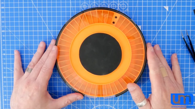
The design is something [Seon] has refined gradually over time, having built two initial versions of the turntable before finally feeling ready to do a wider public release with version 3. It consists of a rotating caddy that has radial slots that hold all the tiny SMD parts, that can be labelled for easy parts identification. There’s also an acrylic window that ensures only one segment of the caddy is open at a time, to avoid accidentally dropping similar, tiny looking parts into adjacent slots – a big improvement over the first design. There’s then a smaller rotating central pad upon which a PCB can be placed, ready to receive parts.
Files are available on Github for those wanting to build their own. [Seon] does a great job explaining how the final design came about, after populating hundreds of boards on his earlier designs and learning their limitations. If doing it by hand just doesn’t cut it for you, though, you can always built a fully automated PnP.


Very VERY cool. Thanks for sharing this.
Great design, I love it.
If I had to build one I’d probably add some small magnets into the rotating tray (one in front of each bin), and one magnet on the case, so there would be some tactile “teeths” that would slightly lock the tray in place and aligned with the window. I think that might make it even easier to use.
That’s a lot of magnets. I think it’d be easier to do the cogging mechanically, by put an indentation in the wheel on the edge or bottom and have a small silicone nubbin or wiper. You might not get the same fast spinning, but if you’re loading your components properly, you should only need the advance the tray one window at a time.
The real question is how long before some adds a stepper and an Arduino or Pi with an Alexa integration, and you tell Alexa which window to turn to…
Indeed that would be a lot of magnets, but small magnets such as this are pretty cheap and I usually like the tactile feel that they provide, more than a mechanical teeth. Response can be fine-tuned by simply moving the fixed magnet closer or further away.
You only need one magnet, on the lid. You can use screws on the bottom. Magnets attract steel as well.
Couldn’t you just make a system like a caliper?
Let’s say you have 10 magnets all aroud the big circle. Instead of having one magnet on the base to stop the rotation, you could have 10 magnets, equally separated so that, it divides by 10 the mouvement.
Now with 20 magnets you get 100 positions.
A quick look of the build, it has 48 positions. So let’s make 8*6 (you could decompose it differently, 2*24, 3*16, you name it, it’s just for the example), that means 8 magnets all aroud your circle (one magnet every 45°) and 6 magnets on the base spaced 45/6= 7.5°.
So with 14 magnets you get te job done.
If I understand correctly you would place lets say 4 magnets on the top, diving the circle into 4 parts (so 90 degrees) then on the bottom you would place another 4 magnets in between the magnets on the top so that they evenly divide the 90 degree arc?
Perhaps one or two magnets and a aperture grill to provide the detent action.
Great design!
The good thing is, in case your component are wet, you can spin them fast enough that they’ll eject all their water.
A long time ago I had an interview at an electronics manufacturer that used a manual pick and place system that incorporated an idea like this. At that time it was through-hole so bigger components. The station had a series of rotating bins, but instead of moving them manually a computer rotated the bin so the next part to be inserted was available to the operator. It also turned on a light by the bin so they knew which bin to pull the part from. The computer also controlled an aimable light that shined on the spot of the board where the part had to go. So the operator would take the part from the bin that was presented to them, put it in the spot where the light showed them it had to go, and then press a button to go on to the next part. Pretty cool system for cases where you weren’t doing a huge volume of the same board.
Very much turning a human into a robot arm there, sounds like a well worked system. No thinking or understanding required, just follow the pretty light…
Wonder how many errors such a system creates – a human that has to pay attention is likely to catch mistakes, but being human is also prone to error, the human not having to think about the what and whys of what they are doing just won’t catch a mistake, which is why you hear stories of components forced in the wrong places, orientations etc, if it can sort of fit the human just follows the instructions without engaging brain…
Computer assisted assembly worked very well, advanced versions even projected a part outline with polarity markings at the right spot. The use of these systems drastically increased productivity and contributed to the price drop of consumer electronics in the 1970s/1980s.
The light indicator which shines on the PCB also would blink if there was a polarity you were supposed to watch.
I ran one back in the early 00’s for a short time. Pretty cool. Rarely had issues and you could stuff a board pretty fast. Place the part…push a pedal and go on to the next part.
Usually these were used past the autoinsertion through hole stuff (resistors, caps, diodes) but just before the wave solder.
Clever design, but some ESD concerns:
Acrylic is quite bad w.r.t. ESD. “acrylic supports the accumulation and discharge of up to 20,000 volts” https://www.terrauniversal.com/blog/static-dissipative-pvc-vs-acrylic/ (no affiliation).
Passives – ok, but MOSFETs and other sensitive devices could suffer.
Consider an ESD dissipative printer filament (sometimes we use a zinc rich spray paint coating instead) and maybe a printed cover from the same material. If the compartment labels could be externally located, it might not be necessary to visualize the entire carousel through a clear cover.
Some further thoughts: A 3D printed cover (acrylic replacement) could have the same footprint as the acrylic, but have an open, spoke-like structure near the perimeter. On the underside, a window material of, typically pink or blue (hey, I don’t judge) anti-static, poly bag material could be attached. This is the same material that the parts were likely shipped in. It would permit viewing all compartments while retaining the components and, hopefully, not destroying any in the process.
For the ESD concerns one could also use ESD acrylic ( e.g. https://www.plexiglas.de/en/products/europlex/europlex-sdx-sdx-f ).
Sadly the design does not work on an common prusa mini which has a printing area of 180x180mm^2 – a down scaled design would be really nice ;)
Extremely cool. I am a huge fan of making such tools and jigs to make life easier.
The only thing I would have wished this had is a gear to rotate the inner table (containing the PCB) with a higher rotation ratio. This is so that it would be easier to rotate the board 180 degrees quickly without physically making the 180 degree rotation by hand. Of course, there are always aspects that can be improved. But this design is simplistic and very good as it is.
Instead of bearing you could use small flat step motor of kind easily salvaged from flatbed scanners. Commonly they have 1.8 or 0.9 degree step (200 or 400 steps per revolution) which give satisfactory ticking feel when manually rotating and holding set position. You may stop here or keep going.
You have room for further expansion. Speaking of motor – why not motorize it? All you need is mechanical or optical encoder. Gray code 3D printed grooves and tiny micro switches with rollers or encoder bands printed on paper glued to inner wall and optical sensor from mouse (easy hackable). You could add simple UI with two buttons and LED – toggle tray state to used/not used in current project and clear all. Your turntable when moved will stop only on relevant storage compartments for actual work.
Then you are open to more automation. For example synchronize your BOM list with one or several part cartridges and have next/previous navigation and readout on your laptop, smartphone or dedicated screen if you insist to have it as independent device.
There are endless possibilities, I’ve got several more ideas while writing it.