A Not-So-Alarming Clock

By and large, alarm clocks (including phones that double as alarm clocks) are annoyingly alarming. If it’s not the light or the sound, it’s both. Yes, we know that’s the point of an alarm clock, but sometimes life presents opportunities to check the time and/or the weather and sleep in a little bit longer based on the result. We don’t know about you, but loud noises and eye-blasting light are not conducive to getting back to sleep, especially if you’re a light sleeper.

In [Stavros Korokithakis]’ case, if it’s a tennis practice morning but it’s raining, then it’s no longer a tennis practice morning and he can go back to sleep for a while. A phone seems perfect for this, but the problem is that it provides too much information: the phone can’t check the weather without the internet, and once it has internet access, a bunch of eye-opening notifications come flooding in.

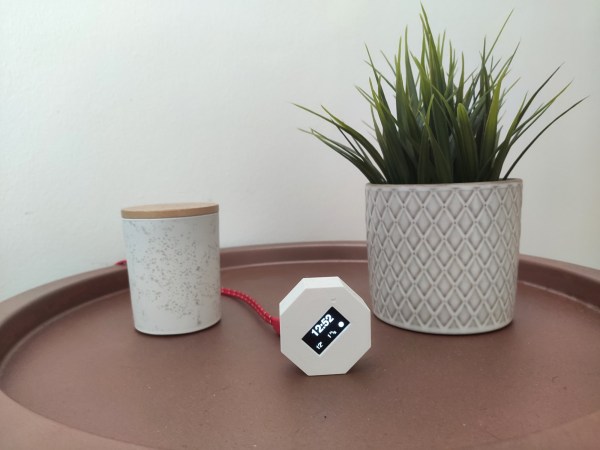
[Stavros] had a long list of must-haves when it came to building the ultimate alarm clock, and we can totally get behind that. He needed something smarter than the average off-the-shelf clock radio, but nothing too smart. Enter the ESP8266. As long as it has an internet connection, it can fetch the time and the weather, which is really all that [Stavros] needs. It gets the current temperature, wind speed, and forecast for the next two hours with the OpenWeather API, and this information is converted to icons that are easy to read at a sleepy, one-eyed glance at the OLED.

Adaptive brightness was high on the list of must-haves, which [Stavros] solved by adding a photoresistor to judge the ambient light and adjust the OLED screen brightness appropriately. And he really did think of everything — the octagonal shape allows for the perfect angle for reading from bed. There’s just one problem — it can’t accept input, so it doesn’t actually function as an alarm clock. But it makes a damn good bedside clock if you ask us.

If you really want to start the morning right, use a winch to yank the covers off of you.

Via Adafruit

Retrotechtacular: Design For Assembly, 1980s-Style

To get its engineers thinking about design for assembly back in the 1980s, Westinghouse made a video about a product optimized for assembly: the IBM Proprinter. The technology may be dated, but the film presents a great look at how companies designed not only for manufacturing, but also for ease of assembly.

It’s not clear whether Westinghouse and IBM collaborated on the project, but given the inside knowledge of the dot-matrix printer’s assembly, it seems like they did. The first few minutes are occupied by an unidentified Westinghouse executive talking about design for assembly in general terms, and how it impacts the bottom line. Skip ahead to 3:41 if talking suits aren’t your thing.

Once the engineer gets going on the printer, though, things get really interesting. The printer’s guts are laid out before him, ready to be assembled. What’s notably absent from the table are tools — the Proprinter was so well designed that the only tool needed is a pair of human hands. And they don’t have to be particularly dexterous hands, either — the design favors motions that are straight down, letting gravity assist the assembly process and preventing assemblers from the need to contort their bodies. Almost everything is held in place by compliant mechanisms built into the plastic parts. There are a few gems in the film, like the plastic lead screw that drives the printhead, obviating the need to string a fussy timing belt, or the unique roller that twists to lock onto a long shaft, rather than having to be pushed to its center.

We found this film which we’ve placed below the break to be very instructive, and the fact that a device as complex as a printer can be assembled in just a few minutes without picking up a single tool is pretty illustrative of the power of designing for assembly. Slick designs that can’t be manufactured at scale are all too common in this age of powerful design tools and desktop manufacturing, so these lessons from the past might be worth relearning.

Continue reading “Retrotechtacular: Design For Assembly, 1980s-Style”

Driving Upside Down With An RC Fan Car

We’ve all seen those tiny little RC cars that can climb walls thanks to the suction generated with fans. Their principle is essentially the opposite to that of a hovercraft. [Engineering After Hours] wanted to build his own RC car that could do the same, driving upside down and generating huge amounts of grip.

The build is based on a Traxxas RC car, but heavily modified for the task. An undertray is crafted, with ducts feeding a pair of twin 50mm electric fans. A skirt is fitted around the edge of the undertray, helping create a seal to maximise the downforce generated. This skirt is the area of much engineering effort, as it must form a good seal with the ground, particularly over minor pertubations, without creating undue levels of friction. Suspension components correspondingly need to be beefed up to stop the car bottoming out with the huge downforce generated by the fan system.

After much experimentation, the kinks are worked out, and the car is able to drive upside down successfully. It generates far more downforce than earlier wing experiments from [Engineering After Hours], as expected – with a tradeoff of higher weight and complexity. With the plan to create an RC car capable of huge lateral acceleration, we can’t wait to see what comes next. Video after the break.

Continue reading “Driving Upside Down With An RC Fan Car”

Orphaned Gimbal Gets Second Chance To Fly

A reality of flying RC aircraft is that at some point, one of your birds is going to fall in the line of duty. It could get lost in the clouds never to be seen again, or perhaps it will become suddenly reacquainted with terra firma. Whatever the reason, your overall enjoyment of the hobby depends greatly on how well you can adapt to the occasional loss.

Based on what we’ve seen so far, we’d say [Rural Flyer] has the right temperament for the job. After losing one of his quadcopters in an unfortunate FPV incident, he decided to repurpose the proprietary gimbal it left behind. If he still had the drone he could have slipped a logic analyzer in between its connection with the motorized camera to sniff out the communication protocol, but since that was no longer an option, he had to get a little creative.

Figuring out the power side of things was easy enough thanks to the silkscreen on the camera’s board, and a common 5 V battery eliminator circuit (BEC) connected to the drone’s 7.4 V battery pack got it online. A cobbled together adapter allowed him to mount it to one of his other quads, but unfortunately the angle wasn’t quite right.

[Rural Flyer] wanted the camera tilted down about 15 degrees, but since he didn’t know how to talk to it, he employed a clever brute force solution. After identifying the accelerometer board responsible for determining the camera’s position, he use a glob of hot glue to push the sensor off of the horizontal. Providing this physical offset to the sensor data caused the camera to automatically move itself to exactly where he wanted it.

Continue reading “Orphaned Gimbal Gets Second Chance To Fly”

Brilliant Brick Prototyping

Have a rusty collection of protoboards wired together that would benefit from mechanical support? Working on putting together a robot and need to attach PCBAs without drilling holes, zipping a cable tie, or globing hot glue? Add some stud holes with [James Munns]’ Brick Mount! This isn’t the first time we’ve seen an interface between everyone’s favorite Nordic building system and circuitboards, but this implementation has the elegance we’ve come to expect from [James]’ software work.

4×8 Feather Medium protoboard

The project repository contains two things: a KiCad library with components for holes in standard patterns and sizes (1×1, 1×2, etc) and a series of protoboards made with those hole components. The protoboards feature a couple common elements; QUIIC connectors for easy chaining between them and holes in the middle or edges for easy mounting on studs. Some are intended to be carriers for Feather-format PCBAs (very convenient!) and others are primarily undifferentiated prototyping space. Of particular note is the “medium” Feather breakout seen to the left, which incorporates clever cutouts to make it easy to wires down under the board so it can be mounted flush against another board.

The thesis here is that getting custom PCBs fabricated is easier and less expensive than ever before. So easy and inexpensive that fabricating customized protoboard to use in one-off projects is cost-efficient enough to be worthwhile. Waste concerns aside this does seem like a great way to level up those temporary projects which find a more permanent home.

The Bus That’s Not A Bus: The Joys Of Hacking PCI Express

PCI Express (PCIe) has been around since 2003, and in that time it has managed to become the primary data interconnect for not only expansion cards, but also high-speed external devices. What also makes PCIe interesting is that it replaces the widespread use of parallel buses with serial links. Instead of having a bus with a common medium (traces) to which multiple devices connect, PCIe uses a root complex that directly connects to PCIe end points.

This is similar to how Ethernet originally used a bus configuration, with a common backbone (coax cable), but modern Ethernet (starting in the 90s) moved to a point-to-point configuration, assisted by switches to allow for dynamic switching between which points (devices) are connected. PCIe also offers the ability to add switches which allows more than one PCIe end point (a device or part of a device) to share a PCIe link (called a ‘lane’).

This change from a parallel bus to serial links simplifies the topology a lot compared to ISA or PCI where communication time had to be shared with other PCI devices on the bus and only half-duplex operation was possible. The ability to bundle multiple lanes to provide less or more bandwidth to specific ports or devices has meant that there was no need for a specialized graphics card slot, using e.g. an x16 PCIe slot with 16 lanes. It does however mean we’re using serial links that run at many GHz and must be implemented as differential pairs to protect signal integrity.

This all may seem a bit beyond the means of the average hobbyist, but there are still ways to have fun with PCIe hacking even if they do not involve breadboarding 7400-logic chips and debugging with a 100 MHz budget oscilloscope, like with ISA buses.

Continue reading “The Bus That’s Not A Bus: The Joys Of Hacking PCI Express”

Transmit Your Gaze To This Fiber Optic LED Lamp

Call us easily amused, but we think it’s pretty amazing what can be done with a microcontroller, some RGB LEDs, and a little bit of plastic. Case in point is [andrei.erdei]’s beautiful and quite approachable fiber optic LED lamp. It’s a desktop-friendly version of a similar piece [andrei] made that is roughly nine times the size of this one and hangs on the wall. The build may be simple, but the product is intricately lovely.

We really like the visual density of this lamp — it’s just the right amount of tubes and strikes a balance between being too sparse and too chaotic. As you might expect, there’s an Arduino and some RGB LED strips involved. But the key to this build is in the 16 pieces of side-glow plastic fiber optic tubing. Side-glow is designed to let light escape along the length of the tube as opposed to end-glow, which is made to minimize light loss from one end to the other like a data pipe. This allows for all sorts of fun effects, and you can watch [andrei.erdei] go slowly and soothingly through the different colors and modes in the demo video after the break. Make sure you watch long enough to see the tubes move like the old Windows 3D pipes screensaver

Already have too many knickknacks and wall hangings? You’re missing out on prime real estate — the ceiling. Check out this fiber optic ceiling installation that reacts to music.

Continue reading “Transmit Your Gaze To This Fiber Optic LED Lamp”