Those of us who work on the road have a constant dread of being stuck somewhere without power, facing a race between a publication deadline and a fast-failing laptop battery. We’re extremely fortunate then to live in an age in which a cheap, lightweight, and efficient solid-state switch-mode inverter can give us mains power from a car cigarette lighter socket and save the day. Before these inverters came much heavier devices whose transistors switched at the 50Hz line speed, and before them came electromechanical devices such as the rotary converter or the vibrating reed inverter. It’s this last type that [Robert Murray-Smith] has taken a look at, making what he positions as the simplest inverter that it’s possible.
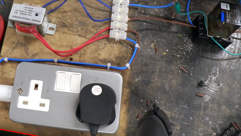
If you’ve ever played with relays, you’ll probably be aware that a relay can be wired as a buzzer, and it’s this property that a vibrating reed inverter harnesses. He takes an octal relay and wires it up with a small mains transformer for an immediate and very cheap inverter. It’s not perfect, as he points out the frequency isn’t right. The relay will eventually wear out unless the arcing problem is improved with the addition of a capacitor. But it does make a rough and ready inverter if you find yourself in a MacGyver-style tight spot with only your junk box for salvation.
If inverters pique your interest, it might benefit you to know how they work.


Having been in the phone business for most of my life I I frequently ran in to these in telephone exchanges and with electro mechanical PBXs. Their contacts were tungsten, and desigined for continuous duty.
Yes this takes me right back to interrupters that I used to make out of old relays, when I was a boy. Some of them have adjustable contacts so you can tune the amplitude. The back EMF from the relay coil could give your friends quite a jolt!
I still have some old telephone relays, hmmm.
But do you still have any old friends?
Nowadays, they’re all old!
B^)
Or dead, from electrocution!
I used to have an old car (1948 Austin 16) Which had a valve radio. There was an electromechanical vibrator circuit in a separate box that was used to boot up some valves to create a valve oscillator to drive the grid(?) voltage transformers of the other rest of the system.
The oscillator made too much RF noise to run continuously in this application, but it only took a few minutes to get things going.
Now, that’s ingenious! A vibrator to bootstrap a multivibrator.
I have an old military radio that has a vibrator in it (GRR-9) but the thought of using it to bootstrap a more reliable oscillator apparently never occurred to the designers.
Very clever engineering.
Parity error on device: Brain.
It’s a GRR-5
But… 5 and 9 have the same parity.
Well, now I want to know if I can get a relay-based switch running in a resonant zero-volt switch configuration, like a Class E amplifier. No arcing, higher efficiency than a simple snubber.
Something handy to know when building electronics from the ground up.
I do think that it’s funny to invert 12Vdc to 120Vac just to transform/rectify it right back down to 12Vdc. You see this same thing at amateur radio field day events all the time. The losses involved are pretty big, though it is often exactly what is needed to keep a laptop going in the field. Not so much with a ham radios, most of which have 12Vdc power inputs.
Just an observation, not a critique. Ya gotta do what ‘cha gotta do.
12>20V boost converters to supply laptops are pretty easy to find, though it often means you need to know which end of a soldering iron to hold to apply the correct mating plugs. Newer “smart” plugs (e.g., USB-C) also require a bit of mediating electronics to negotiate the connection for you.
Another alternative is to skip the “AC” part in the conversion: use an inverter to produce 100-160 Vdc and feed that to the laptop supply: it’s more efficient, lower noise, and essentially zero leakage current. The laptop supply (or any SMPS for that matter) is perfectly happy and even runs cooler on DC: I^2 losses are lower, filter losses are lower, and there’s zero loss due to capacitor ESR.
A modern small inverter doesn’t operate at (e.g.) 60 Hz: it uses much higher frequency to produce 160Vdc, and then chops *that* to make the output 60 Hz. It’s easy to neuter that chopper to make clean DC instead.
I should qualify the “any SMPS” statement: those that use thyristor angle control (looking at you, Lambda) or otherwise depend on the zero crossings (like some power factor correction circuits) will get a bit confuddled.
It seems most pfc circuits do alright on DC. They just work like a boost converter.
Some pc power supplies use a voltage doubler to run on 110V, so they need 300VDC since the doubler won’t do anything.
True that. Hard to find sub-100W supplies that use doublers these days though. At least they are easy to tell: they have a manual 120V/240V switch.
I think you’re missing the entire point of the article. It wasn’t “build the smallest most efficient inverter”, it was “the simplest inverter you can make”
Not sure I’d consider homebrewing an SMPS the simplest. The one in the article could be build with junk from almost any tinkerer’s garage.
I think you’re replying to the wrong post. My post was a comment on DainBramage’s observation, not on the OP.
And nowhere here is anybody advocating homebrewing a SMPS.
Model T Fords (1906 to 1927) used a Multi-vibrator in the Low tension Spark Circuit of each Ignition Coil to get Multiple Sparks out to the Plugs. The ‘Points Gap’ was a setting on Each Ignition Coil box.
In the Battery Powered T’s, you could here the ‘Buz’ of the Coils when the Car was idling, or being Started.. Generally as the RPM came up, the Buzz got drowned out me Noise.
For the Non Battery T’s you only got one bite at the apple while pulling through the Crank, till it started running. After that the Low tension Mag made enough Juice to Buss the Coils.. The hard part is getting the T Started, things had to be perfect the first time.
Cap
Vibrators were common in car radios before transistors came along. They were used to step up battery voltage to plate voltage for the tubes. When you turned the radio on you could hear the vibrator buzz while the tube filaments were warming up. The vibrator looked like a tube in a metal can.
When my Dad got a 1957 chevy to relive his youth, I volunteered to get the tube radio going. He insisted that music from that radio was the best sounding music he ever heard (early tube sound enthusiast?). Although the radio bezel on the dash was compact, the chassis behind the dash was big and weighed about 20lbs. I was amazed they would go to that much trouble to have an AM-only radio onboard. Anyway, the power supply had a metal can in a tube socket that internally was a relay with a weight on the end of the arm and some spark suppressing caps. The weight and spring were tuned to about 50hz. The transformer primary center tap was 12V, and each side was alternately grounded by the relay to create 12V AC. The secondary was used for the tubes’ plate supply. The high voltage rectifier was a tube.
My Dad came home one day with a brand new 57 Chevy Belair. It was the first car we had with a clock. The clock was mechanical, but it was automatically wound by a DC motor. It was a great car for dates.
This apparatus is indeed beautiful in its simplicity for teaching how switch-mode power supplies work. It will also serve brilliantly as a “Marconi era” wide-band radio transmitter and RF noise generator (aka jammer). To supplement the recommended arc-snubbing capacitor, a metal can went around each old “tube” car radio vibrator, serving as a Faraday cage to keep the FCC “airwaves police” from knocking on your door.
When I was a teenager, I used to work at a two way radio shop. We’d see some pretty old radios too, including some Motorola T-Power and even old GE Progress Line radios. They were almost entirely built around tubes. It was commonplace in the “Frog-Line” radios to have the Vibrator wear out.
Those things would live a hard life, bouncing around in the trunk of a taxicab with a control unit in front. And yet, we kept them working. But in fairness, I replaced a lot more capacitors than I did Vibrating reed inverters. So in the scheme of what brought those radios in to the shop, that was not the worst thing there was.
When I was a teenager, I had a Progress Line (I haven’t heard or thought that name in decades) set up for the .16/.76 2M repeater in Indianapolis. I had it in the trunk of a ’69 Dodge Dart. It worked quite well, but drew a lot of current. My call was WD9GHJ, I let my license lapse many years ago.
Perhaps the most novel application for this was American Flyer’s air chime whistle in the ’50s, which used a vibrating reed to generate high-frequency current, which was piped through the rails to a speaker in the locomotive.
You can accomplish something similar with a transformer and a motor. I used to create a hand shocker this way when I was 10. Battery powers the motor, the transformer is inline with that. As the brushes briefly lose contact, the voltage spikes down. This creates the AC that the transformer bumps up. By controlling the mechanical resistance of the motor, you control the frequency. This would last longer than a relay.