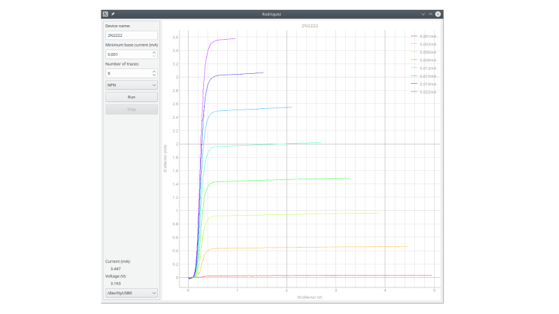
In response to an online discussion on the Electrical Engineering Stack Exchange, [Joseph Eoff] decided to prove his point by slapping together a bare-bones IV curve tracer using an Arduino Nano and a handful of passives. But he continued to tinker with the circuit, seeing just how much improvement was possible out of this simple setup. He squeezes a bit of extra resolution out of the PWM DAC circuit by using the Timer1 library to obtain 1024 instead of 256 steps. For reading voltages, he implements oversampling (and in some cases oversampling again) to eke out a few extra bits of resolution from the 10-bit ADC of the Nano. The whole thing is controlled by a Python / Qt script to generate the desired plots.
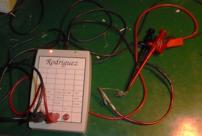
While it works and gives him the IV curves, this simplicity comes at a price. It’s slow — [Joseph] reports that it takes several minutes to trace out five different values of base current on a transistor. It was this lack of speed that inspired him to name the project after cartoon character Speedy Gonzales’s cousin, Slowpoke Rodriguez, AKA “the slowest mouse in all of Mexico”. In addition to being painstakingly slow, the tracer is limited to 5 volts and currents under 5 milliamps.
[Joseph] documents the whole design and build process over on his blog, and has made the source code available on GitHub should you want to try this yourself. We covered another interesting IV curve tracer build on cardboard ten years ago, but that one is much bigger than the Rodriguez.


>He squeezes a bit of extra resolution out of the PWM DAC circuit by using the Timer1 library to obtain 1024 instead of 256 steps.
You can get up to 16 bits of resolution by summing the two 8-bit timers’ PWM channels together in a 256:1 ratio. The reason why it’s “up to” is because actually getting to 16 bits requires trimming the circuit to be precise and stable down to 15 parts in a million, which is complicated.
In other words, no: your 16-bit DAC isn’t really accurate to 16 bits either because the output drifts around, and you probably also have a noise floor corresponding to something around 10-15 bits for a common cheap chip. The DAC tries very hard to change the output very slightly, but the difference gets lost in analog circuit noise.
That said, this would be an excellent case to use a ramp circuit to generate the voltage, because that shifts the problem from generating a precise voltage by PWM to counting time, which comes easy to a MCU that’s running at tens of MHz.
There are many ways to do it. You could build it to translate a single pulse width to a voltage and add them up until you reset the circuit, or you could have a free running circuit and just snap samples along the way, going as slow or as fast as you want:
http://www.circuitstoday.com/wp-content/uploads/2009/09/555-ramp-generator.jpg
Or see:
https://www.analog.com/media/en/technical-documentation/data-sheets/LTC6993-6993-1-6993-2-6993-3-6993-4.pdf
Page 22. “Staircase Generator with Reset”
The actual staircase is generated by U2, D1, R11, C1 which form a simple sampling integrator that turns a single pulse width into a constant voltage and adds subsequent pulses together. The voltage output isn’t linear with respect to time, but that doesn’t really matter because all you care for is making small incremental steps and measuring the output to plot it. The advantage is that there’s no ripple in the output.
U3 is used to buffer the output (and can scale/shift the level if so desired). U4 resets the ramp. The op-amps can be just about anything, don’t need to use the LT parts, and the special timer chip isn’t needed because you’ll be doing the reset with the uC.
If you want, you can improve on this setup by using a current mirror to pass a constant current into C1, which will result in a constant voltage rise over a constant width pulse. The example below discusses current sinks, but these can be flipped around to current sources easily by using PNP transistors instead of NPN transistors.
https://wiki.analog.com/university/courses/electronics/text/chapter-11
Just use an opamp integrator. It is simple and output is linear.
Connect the non-inverting input of the integrator to mid rail and drive the integrator input with a GPIO and select ‘0’ or ‘1’ or tristate (to hold value).
It doesn’t hold its voltage though, so over-sampling becomes more difficult because you’re doing it against a changing voltage.
Point being, the tri-state is subject to the leakage current of the uC and the input bias currents of the op-amp. The peak holding integrator will be subjected to less error (still drifts over seconds though).
Oh, and the reason why you would gang the two 8-bit timers together is because using Timer1 to generate 16-bit PWM directly limits the rate to something like 240 Hz, while the 8-bit timers can run at 62.5 kHz – except the Arduino libraries break if you change the clock pre-scaler.
Anyways, you could set the Timer1 to 8-bits and use its two PWM channels just the same.
Correction: not two 8-bit timers but the two PWM channels (A and B) of the Timer0 or Timer1
Consider how curve tracers are used, though: they aren’t for measuring the precise characteristics of a device, but for comparing the characteristics of the device under test with some “typical” curve for that device type, or to determine if it meets specs, or to gather enough data from a large enough sample of devices to generate those typical curves in the first place. So extreme accuracy is not the first priority, and therefore, neither is the number of bits. Speed is far more important, which is why automatic curve tracers that displayed a number of curves for a device in almost flicker-free real time were developed in the first place. In the 1960s, i might add. Note that these displayed their results on CRTs, with an effective resolution of not more than 10 bits anyway. To me, a curve tracer that takes minutes to characterize a device is about as useful as a doorbell that rings minutes after the button is pressed.
Maybe it is a good idea to read the stuff Ronald Dekker’s uTRacer tube tracer did to speed up things. I have build one and it’s awesome. https://www.dos4ever.com/uTracer3/uTracer3_pag0.html