In advanced engineering circles, the finite element method — or, more commonly, finite element analysis — is a real staple. With the advent of more powerful home computers, though, even your home projects can benefit. The technique itself is very general, but you usually see it used for structural analysis. However, you might wonder how well it corresponds to reality. That is if analysis shows a segment of your part is weak (or strong) does that hold true when you actually build the part? [Fiveohno] wondered the same thing and decided to do some testing, which you can see in the video below.
Of course, like any simulation, the accuracy will only be as good as your data input and model. But if you work carefully, it should match up pretty well to the real world, so it is interesting to see the results of a real-world test. In fact, a video from Solidworks that shows a similar part points out — inadvertently — what not to do. For example, the force used in that analysis was too low and at a point where the part was at relatively low stress instead of at the maximum stress.
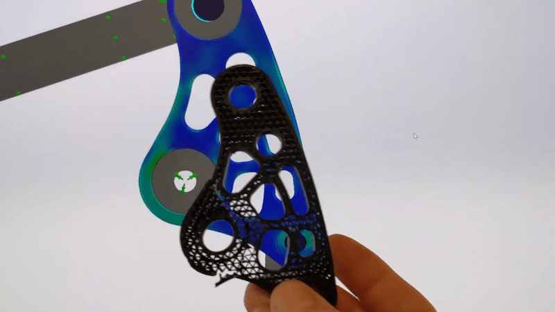
In general, the finite element method deals with solving differential equations. It is a complicated topic, but in a nutshell, you break up a part into many small pieces (a mesh) and then work with simple equations that represent just that small piece. In the case of the experiment, the model was for a suspension rocker link for a bike that receives a lot of stress.
The actual experiment is nearly 11 minutes in. Enough stress causes the part to break. Then looking at the analysis, you can see the physical damage matches pretty closes to the simulation results.
We love seeing real life compared to virtual simulations. If you want to learn more about finite-element analysis and you weren’t at our Remoticon, you can catch the replay. If you want to apply the technique to your infill patterns, we’ve seen it done.


The whole point of FEM is to avoid solving differential equations. You solve a [rather large] system of linear equations.
It is a computational tool that gives you numerical approximations. There is still the math involved in setting up the model. It also let you build real life objects and not confined you to special cses like spherical chickens. You can selectively control the computational needs vs accuracy by using finer meshes at the area of interest – kind of like computer graphics.
No, you are still solving PDEs with numerical discretization. Linear equations arise from linearization, typically by integrating basis functions that allow you turn integrals into sums. There various weighting functions from simple piecewise constant ones to more smooth polynomial spline functions. A lot of mechanical engineering is concerned with small-deformation which means you can use linear stress/strain approximations, but to do large deformation analysis you need non-linear models. Those are turned into linear systems eventually using Newton-Raphson linearization typically, but you might do it many times per-time step.
FreeCAD’s FEA workbench is really impressive for a free program. I’ve found it can be pretty difficult to accurately tell the model where to put the loading forces, and small issues with that have big effects on the result. Like, trying to model how force moves from a half circular race through a bearing ball into another half circular race is really not easy.
But if you can define your load points and stress points well, it’s sure a nice way to see generally where your design inadequacies are.
In one sense, ANY digital method of calculation is approximate and thus related to FEA (e.g. long floats are approximations of the “real” numbers). But, if the problem is not convex (see https://en.wikipedia.org/wiki/Convex_optimization), then even approximation methods lead to a solution “in the neighborhood” of the real thing. Don’t you hate it when you calculator can’t handle numbers well and show imperfect solutions? And, how do you know that? Or why?
OTOH isn’t manufacturing a part just another approximation? There are difference in dimensions, surface quality, material values, heat influence (during manufacturing), etc etc. Producing multiple parts and pairing those imperfect part with each other introduce more approximations. The pairing process is another imperfection. And so on, and so on.
Just apply a security factor of 8,5397 and all is good. And don’t use 7CrMoVTiB10-10.
To a degree, one can make some approximations to the strength of a given piece by hand. Calculating the cross sectional areas of various joints, the stresses applied on them, and also considering hoop stresses. It is however a lot of tedious work for more complex designs, so sticking to simpler stuff is generally advised if one wants to give it a crack the old fashioned way. And one can also carve out “redundant” material from a piece by largely using rules of thumb. But one will need to leave a fairly decent margin, so the weight savings won’t be huge.
Finite element analysis can though greatly reduce the needed margins if one’s input values and material properties are sufficiently accurate. Though, manufacturing tolerances and material quality will add back some of that margin, otherwise a real part would likely break due to not being ideal.
Though, for both manual and computerized approaches, if one starts out with incorrect values, then both will give incorrect method. But the important thing in engineering isn’t absolute accuracy, but rather sufficient accuracy for the application. And for most practical implementations, there will always tend to be some degree of safety factor as well.
FEA assumes perfect surfaces, so you have to keep your wits about. An innocent looking scratch or gouge on the surface doesn’t reduce the cross-section by any meaningful amount, but over multiple stress cycles it opens up into a crack that crosses the material and leads to a failure anyways – catastrophically so, since you’ve optimized the material away from everywhere else.
Fracture mechanics can be handled in many FEA packages, just not consumer stuff like Solidworks. ANSYS for instance.
finite element analysis is a double edged sword. on one hand it allows you to optimize structural designs. on the other hand, allows extreme cost cutting through material reduction to the point where you got a spindly part that will fail if you look at it crosseyed.
The issue is that it is only optimized to a specific load condition. It’s like a coke can can survive hundreds of pounds of load from the top, but touch the side and it crumples.
The fea presented will work great in a specific orientation and load, but as the loads change as it rotates, it will quickly overstress an area that wasn’t optimized for that load condition. The imperfections and infill will also impact the capability for the FEA to match reality (the FEA shows a solid infill!)
It’s better practice to vary the load inputs a bit to see if there is additional reinforcement required to prevent failure during some transient point or slop in operation
FEM in some situations may be the only tool that allows you to grapple with a problem. Years ago I was able to use it to iteratively design a structure that involved a complex mix of conductor+dielectric+air-gap regions that held its set of desired microwave properties within the desired tolerances over the entire range of manufacturing variations. I can’t think of any other method that would have been up to the job.
One of the areas I discovered that required caution is the choice of boundary conditions. At least one tool vendor turned out to default to an inappropriate surface current approximation irrespective of the thickness of a metal component. In some situations you had to roll your boundary interface in order to get correct results.
They were using FEM tools for simulating magnetic fields inside a motors, LIM etc at my University. It is not something you can measure easily at a good resolution on a running motor. :P
Still waiting on SolidWork’s ‘hobbyist/maker’ version.
No lattice structure in his model. His model is invalid to start since it assumes isotropy. Those lattice structures buckle, e.g. nonlinear analysis, plus they make for bulk elastic moduli that will vary with direction. Having done FEA for well over a decade be careful how you interpret things and also constantly revisit whether your model really represents what you think it does.