When it comes to FDM 3D prints and making them stronger, most of the focus is on the outer walls and factors like their layer adhesion. However, paying some attention to the often-ignored insides of a model can make a lot of difference in its mechanical properties. Inspired by a string of [Tom Stanton] videos, [3DJake] had a poke at making TPU more resilient against breaking when stretched and PLA resistant to snapping when experiencing a lateral force.
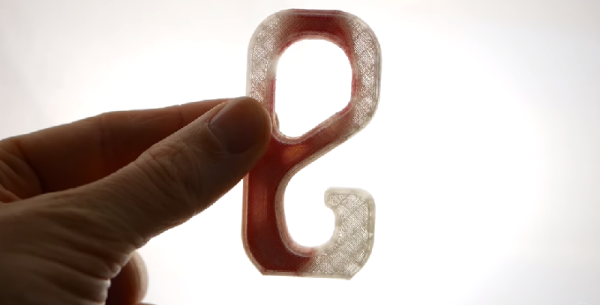
Simply twisting the TPU part massively increased the load at which it snapped. Similarly, by removing the infill from the PLA part before replacing it with a hollow cylinder, the test part also became significantly more resilient. A very noticeable result of hollowing out the PLA part: the way that it breaks. A part with infill will basically shatter. But the hollowed-out version remained more intact, rather than ripping apart at the seams. The reason? The hollow cylinder shape is printed to add more walls inside the part. Plus cylinders are naturally more able to distribute loads.
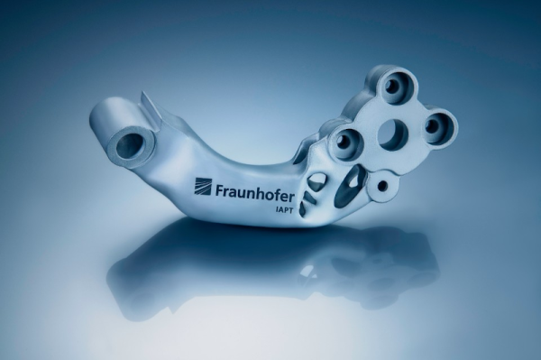
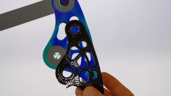
All of this touches on load distribution and designing a component to cope with expected loads in the best way possible. It’s also the reason why finite element analysis is such a big part of the CAD world, and something which we may see more of in the world of consumer 3D printing as well in the future.
Continue reading “Removing Infill To Make 3D Printed Parts Much Stronger”