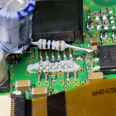
[Doug]’s newly-installed Yaesu FT-891 mobile transceiver failed to power up despite a careful installation, and it turns out to have ultimately been caused by a reversed cable. There’s a happy ending, however. Since the only real casualties were a blown resettable fuse and a badly-burned resistor that damaged the PCB, [Doug] was able to effect a repair. Things could have been worse, but they also could have been better. Damage could have been prevented entirely with some better design, which [Doug] explains during his analysis of what went wrong.
The main problem was that the generic RJ12 cable that [Doug] used to connect radio components had its connections reversed. This would not be a problem if it was used to connect a landline telephone to the wall, but it was a big problem when used to connect the radio components together. According to the radio schematics, the two center wires carry +13 V and GND, which meant that a reversed cable delivered power with reversed polarity; never an optimal outcome.
Once the reversed power arrived at the other end, [Doug] discovered something else. Diodes whose job would be to protect against reverse polarity were marked DO NOT INSTALL, probably to shave a few cents off the bill of materials. As a result, the full 13 V was soaked up by a 1/8 W surface mount resistor which smoldered and burned until a fuse eventually blew, but not before the resistor and pads were destroyed. Thankfully, things cleaned up well and after replacing the necessary parts and swapping for a correct cable, things powered up normally and the mobile radio was good to go.
Curious for a bit more details about mobile radio installations? Check out our own Dan Maloney’s rundown on installing a discontinued (but perfectly serviceable) Yaesu FT-8900R.


In looking at the blog written by the owner, the diode across the voltage regulator, if installed, would only protect the regulator during the few milliseconds of power down time. With reverse polarity 13.8V applied to the circuit, the diode would conduct, frying circuits used by the 3v3 bus. The only way the entire control head could be protected (ones that wouldn’t blow a fuse), would be to place a diode in series with the 10 Ohm resistor.
I am also surprised at the application of such a high voltage to a 3-pin 3v3 regulator. Generally, such a voltage drop would be asking for a failure of the regulator, or at the very least, running very hot.
Reference for the above statements is an application note titled “Linear Regulators, Reverse Voltage Protection” from ROHM Semiconductor: https://fscdn.rohm.com/en/products/databook/applinote/ic/power/linear_regulator/linearreg_reverse_voltage_appli-e.pdf
My favorite part is how the 10-Ohm resistor became a “fuse” before the actual fuse tripped. Seems like a rookie mistake, doesn’t it?
I’m not entirely surprised by the regulator arrangement, though. The 3.3V rail most likely is powering the MCU and wouldn’t need a ton of current, so the power dissipation should be fine. Linears all over to avoid switching noise, of course. Ham units do get very warm, fans aren’t uncommon especially when they run the digital modes.
Reminds me of when I was making my first Hackintosh, based on the original 128K Mac motherboard. I wasn’t thinking straight and I mirrored the power connector on a power cable I had made. I had also done the 128K to 512K upgrade during the build. The mirrored cable swapped 5V and 12V, and it immediately fried all the upgraded DRAM chips. Oddly enough, they were the only victims. After fixing the cable, I was able to put back the original DRAM chips and had a working 128K Mac. Eventually, I got some new DRAM to redo the upgrade. It was an expensive lesson for me at the time.
DRAM tends to fail very quickly and fail short, which protects the other ICs in the path. A great many fried retro computers have been saved because of this, because memory is easy to replace but custom gate arrays are not.
I had this exact failure on a C64 mainboard from a friend. Found it the “classic” way by powering it up and checking which ICs are hot enough to nearly burn my fingers. Replacement was taken from some graphics card, aswell as those are also socketed now. Still have that board around…
There I was thinking my box of 68k Mac SIMMs gathering dust had no practical purpose.
I have seen quite the same issue with an expensive FPGA board (with a kintex 480T, ie 1500$ chip).
There is an fpga connector for loading the bitfile, which is a keyless 20 pins, so can be inserted both way.
And you guess right, one is correct, the other tie the 3.3v to the ground. Instant DCDC converter fried (current limited but cannot take a true short).
I bolched a repair with a 3.3v converter module for a few buck…
Now when I design my own connector I try to make them reversal proof even if there is a key. Looking at you ARM with your 9 and 19 pins jtag…
One of the first things i do with expensive (dev-)boards is to add a fuse and a beefy reverse diode at the input. Thinking about it a “crowbar”-circuit against overvoltage would be a good idea too, but it is more complicated and “expensive” is always relative.
Zeners and unidirectional TVS (SMBJ…, 1.5KE…) can protect against overvoltage and reversal. TVS are preferred, they are designed to take a hefty punch without blowing up.
When I was in school, ever electronics class emphasized Murphy’s law in that (Paraphrasing) “If there are two ways to install a part, it will always be installed the wrong direction at first, so make sure it will survive to the second try”.
There was nothing wrong with the “reversed” cable, except that it was used in an application that doesn’t use normal telephone wiring. The wiring shown in the picture is correct for phone wiring. Not just “not a problem”, but correct. Huh? I’ve been burned by this as well, although not as literally.
Let me explain. Here is how phone cables are intended to work (K=black, B=blue):
W ————- W
K ————- K
R ————- R
G ————- G
Y ————- Y
B ————- B
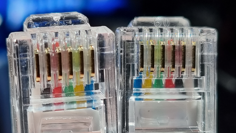
The problem is that phone wires are made with the tabs on the same side of both ends of a flat cable, which means that the wires at one end of the cable will read 1-2-3-4-5-6 left to right as you look at the side with the tab on it, and 6-5-4-3-2-1 at the other end. There are two consequences of this:
1) Every RJ12 telephone cable must be a crossover cable, which is counterintuitive, and
2) “Cable joiners” that are used to extend phone cables can be wired straight through.
Why did they do it this way? As people who have dealt with RS-232 and Ethernet (in the old days) wiring learn, usually the hard way, is that when you use the same kind of connector at both ends of a cable, wiring the connectors straight-through will result in output-output and input-input connections, where what you really want is output-input and input-output. So when you are connecting two devices of the same type, you have to swap pins in order to make it work. This has been such an issue over time, that all land-line phones have bridge rectifiers built in, so that whether the wire is straight-through or crossed-over, the phone will still work. Likewise, almost all Ethernet devices will automatically detect on start up, what the polarity of the device at the other end of the cable is, and reverse the connections when needed, again so that it will work for cables wired either way.
THAT is the take-away message from this. Whenever you use multi-pin connectors that use the same connectors at both ends, this is a potential issue.
I kind of made a mess of that, when I edited it to try to make it more clear. I meant, the wires WILL read W-K-R-G-Y-B at one end and B-Y-G-R-K-W at the other end. Also, when I said “two devices of the same type”, I meant this in the RS-232 sense, where there is Data Terminal Equipment (DTE), which originally meant a Teletype machine, but eventually included computers, and Data Communications Equipment (DCE), which meant modems. A straight-through RS-232 cable was correct for connecting DTE to DCE, but would not work when connecting DTE to DTE, for example, connecting two computers together. For this to work, you needed a special cable (or adapter) that swapped several input and output pins.
Personally, I think that a big part of the problem is that manufacturers of ham radio equipment, despite all of the problems it causes, continue to use inappropriate connector types on their proprietary cables. No RJ series connector should be found on a 2-way radio, ever (IMHO). I have seen them fail so often and in so many ways that I finally invested in a set of crimpers so I could help my buddies fix their microphones and head cables.
Yaesu, Kenwood, Icom, and a bunch of others are all guilty of this, probably saving themselves a dollar or so on their $1000 radios… Oddly, Alinco still seems to use quality locking mic connectors like those found on far less expensive CB radios, at least on some of their models (such as my DR-235).
I feel that you are right about the RJ series, but having special connectors designed would only add on higher costs to already expensive radios. Checking my IC-2000 schematics, I found the same situation, except for one thing. ICOM did not send the full 13.8V to the control head. Instead, there is a 7808 3-lead regulator to drive the control electronics. The nice part about these regulators is that they have a current limit. Unfortunately, ICOM did not incorporate a diode block for mis-wired RJ cable here either. However, with the combination of the 7808 driving the circuit makes the circuit a bit safer.
The use of cables other than the official one isn’t advised with any radio, as mic audio, as well as digital communications, and earphone audio in these cables (ICOM at least). Internal coax is used for the audio to shield it from external interference.
I agree with you about using only the official cable, but I still think that leaving a $0.05 diode out of a $1000+ radio to save money is an awful cheap thing to do. I, for one, wouldn’t mind paying a bit more for a radio that I know won’t go up in smoke when someone plugs the wrong cable into it.
As for the connectors, there are plenty of good connectors already on the market, so they wouldn’t have to design a brand new one. There might even be some that would fit right in place of those dreaded RJ’s, but I don’t know.
When you say “fail of the week”, I assume you mean ‘fail of the week on the part of the designer’… there are so many issues that have bee raised here ranging from a radio so expensive it makes your eyes water, yet not putting a cheap-ass diode in the design… the design in the first place: a resistor smoking before the fuse blew… deciding a stupid pin-out, and then putting it on a RJ11/RJ12…
(Warning: The following is a pedantic rant. Reader discretion is advised.)
It’s a 6P6C modular cable, not an RJ12 cable. An RJ or Registered Jack standard specifies a female connector (and only the female connector), wiring scheme, and signaling protocol. RJ12 specifies a 6P6C modular jack but the 6P6C modular jack is specified by several RJ standards. A 6P6C modular cable can be used with several different kinds of registered jacks, not just RJ12.
(End rant.)
Now [Doug] hedged a bit and described it as a “RJ12 6p6c” cable, so I’ll only take one-half point off.
That being said, I can’t really fault Yaesu for using ubiquitous and low-cost modular connectors as opposed to something that’s proprietary unobtanium or not available for purchase in less than 1,000 units lots, thus making it easy for people like [Doug] to whip up custom cables. The crossed- vs. straight-wired modular cable has also bit me before so I now verify twice (or more) that each pin is going to the right place before applying power.