One of the original ideas behind the RepRap project was for the machines to create their own upgrades. That philosophy is shining brightly in [Ivan Miranda] CNC milling machine project, which has been used to upgrade its aluminum and 3D printed frame components to steel.
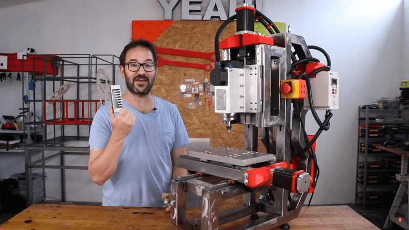
For precision machining on hard metal, machine rigidity is of utmost importance. [Ivan]’s original CNC mill made extensive use of lightweight aluminum extrusions with 3D printed fittings. The machine worked, but the lack of rigidity was visible in the surface quality of the machine parts. The latest upgrade included a completely new frame from welded steel tubing and heavy aluminum mounting plates. The original machine was used to slowly machine slots in the steel tubes to retain the adjustability of the Z-axis. Some of the 3D printed motor mounts remained, so in the second video after the break [Ivan] used the newly upgraded machine to mill some aluminum replacements.
While this machine might not be perfect, we have to respect [Ivan]’s willingness to toss himself in at the deep end and show all failures and lessons learned the hard way. This project was clearly used as an opportunity to improve his welding and machining skills. His fabrication skills have come a long way from mainly 3D printed projects like the giant tracked tank and screw tank.


It’s not a 3D printed milling machine. How many of the functional parts are actually 3D printed?
Did you even read the article, or just judge it on your first 2 seconds of input? The original mill linked in the 2nd paragraph is largely 3D printed with off the shelf parts.
If you’re all “bUt ThE fUnCTiOnAl PaRtS aReN’t” then kindly do one and take your pedantry elsewhere. This is a great project and the bootstrapping aspect that resulted in this new machine is admirable to say the least.
The ball-screw duplex thrust-bearing blocks are plastic. Ahem. . . You know, normally the most expensive parts for the repeatable precision. I am sure the number of broken end-mills will encourage him to look at better designs soon.
Lost-PLA ceramic shell methods or sand-casting can actually make real aluminum, brass, or mild-steel parts. However, there is a bit of a issue when you can’t mill the castings, or run a furnace. This sand+coating binder material is generally better at holding dimensional tolerance on fine details, but one can still expect around 1% part shrinkage on cooling. https://shop.ransom-randolph.com/suspendaslurry-fs-60
Cheers,
=)
Yeah, this doesn’t seem so 3d-printed. If you look up the MPCNC, that one seems pretty good. https://docs.v1engineering.com/mpcnc/intro/#software
If the steel tubing is hollow then try filling it with expoxy mixed with granite to increase the vibration damping / regidity
I use concrete (with a sticky additive) inside steel tubes – works great. The only down side is shifting the whole thing when done (get quite a few meters of 100mm tube filed with concrete and the weight does add up) :-) You can still weld and cut the tubes..
“sticky additive”? Do tell. I doubt we’re talking peel-and-stick concrete wall hooks, but I’m still very interested in learning what additive can make concrete adhere (even) better to steel.
When I was an active carpenter, we used concresive – a two part epoxy. Probably a bit on the toxic side. There are also a number of consumer additives, often used in mortars. Check Home Depot. At least one of them is likely a derivative of Elmers Glue…
I use Bondcrete – https://www.bondall.com/concrete-additives/bondcrete/
You mix it in with the concrete – I have been using it for so long I don’t even measure it, I just put it in till the concrete is the right texture..
It makes the concrete more sticky, and makes it water resistant – both good things in steel.
Ah. OK. We’ve got similar stuff on this side of the planet too. I never considered that it would improve adhesion to steel. Good to know.
This guy just discovered that milling steel involves somewhat stronger forces than printing plastic. Call it entertainment if you want. I call it a waste of resources and time. While he had some other entertaining ideas this CNC construction is no fun to watch.
If you want any kind of CNC don’t follow this example, plenty of good designs available out there to do it correctly, this is not one of them.
Seriously H@D stop giving attention to this level of nonsense. There is much much better out there.
Post links to some resources then.
This is probably the best home built machine I’ve seen on youtube:
https://www.youtube.com/watch?v=mOz9vpfOqxY
About the build of this hackaday project…
I appreciate the enthusiasm and the actual building of something, making video’s and sharing it, but this machine is so badly designed that I actually find it quite sad.
But probably his goals were not to make the most rigid machine he was capable of, but, well who knows.
The part at the back looks designed with no other practice then to improve his welding skills.
If you do want to make a rigid machine then follow these practices:
Do not put those linear rails along the middle of such a big square tube. The top surface will bend under load. Filling the tubes with epoxy granite or just concrete will help a lot here, but you have to take care of the nuts, and threads. Another way is to use narrower tubing (for the width, not the height), use tubing with thicker wall thickness, or weld on a thick strip for mounting the linear rails.
Make your whole construction out of triangles, so put a diagonal brace into each rectangle.
It also looks like he put some “longer bolts” in the holes at the end to prevent the carriages from falling off the rails. This is acceptable for storage (and actually a reasonable idea) but not for the final machine. At the very end of the video it looks like that the first time the machine crashes (hardware, software or G-code error, or even user jogging error) the carriages will be pushed into these bolts by the motors, and the end caps of the linear bearings get destroyed. Having limit switches is a partial solution, but those bolts should never stick out at that place. The proper solution is to make some strong piece of metal that prevents the carriage from going too far, and it should touch the machine in a place where it will do no damage. You also get a few extra cm of travel out of the machine for free, as you can use the whole linear rails.
A possible advantage of this weak construction is that alignment is a lot less critical. Small alignment errors will just get absorbed by the frame that flexes to accommodate these errors.
This other guy also made a serious attempt, and built a decent machine, but he made a bunch of similar errors, and he could have gotten significantly more stiffness out of his machine with minimal design changes:
https://www.youtube.com/watch?v=i4q95Czq7pc
Give it a break, it’s “hack a day”, not “good cnc product for professionals a day”.
There are better CNC designs out there for sure. We’ll be running one in the next couple of days, so stay tuned. :)
But there are also worse, and we enjoy them too. You can learn a lot from failures.
This one? It’s somewhere in the middle, right? Everyone was bagging on his aluminum/plastic mill, but it let him (gingerly) cut the slots he needed in the steel to make the frame for this one. That’s pretty much the definition of functional in my book, and we _do_ like to see the bootstrapping.
I can appreciate doing a project like this for the interest / exercise / learning or because your time is somehow cheaper than the cost of a ready-made machine… but for most of us who just want to get on and machine things the best answer in terms of cost vs time vs results is to just buy a damn mill.
This project certainly demonstrates a few good reasons why it’s not as easy to make a mill (or lathe, etc.) as it is to throw a 3D printer together where there’s very low loads on everything and relatively low accuracy.
It of course depends a lot on one’s time value. I’m earning a very good salary, work overtime for even more money, but if I wanted to buy a good mill, it would still take me a year to earn for it. But working on a mill directly would be actually much better, because it’s more fun than working on the same thing as in job.
Most of us?
I’m pretty sure the difference here is profession vs hobby.
A professional who needs a high quality heavy duty mill to keep food on the table would be a fool to go through this process of 3d printing a weaker one to use for making the parts to strengthen it.
On the other hand a good mill is expensive. On most budgets one might say it would be foolish to spend so much on a hobby item. Further, doing so would be to miss out on a lot of experience that will come in handy when using the mill as well as the pride involved in having made such an awesome device.
To the professional that time is an expense, to the hobbyist it’s profit. To the hobbyist it’s often about the journey more than the destination.
So, how many here do you think are professional CNC operators vs hobbyists? Is it really “Most of [us]”? What’s a “hack” again?
This is far from nonsense, its a bootstrapping process from a mill I’d not touch at all, that really was all extrusion and 3d print, to this one, which is, with a few tiny improvements good enough I’d be happy to have one.
The core design is reasonable, just needs a bit more polish to make it a perfectly good machine for its size and working volume. Could it be better, sure, but the question is could he make a better one with the tools he has. Again I lean into probably, but he certainly couldn’t from what we know of his tools and skills make a better one as easily as he made this one – using his real strengths to make many of the parts and get that functional machine more quickly!
love my Bridgeport….2000 pounds of cast iron. 😎
My comment was more about the headline (and the previous headline for the original mill – whose fUnCTiOnAl PaRtS were also not 3D printed) than the article. Just stating facts. Great project, I agree.
There is serious potential to make a reasonably good mill at a relatively low price, but not like this. Perhaps using resin casting, printed molds and hydrostatic bearings, for instance. Then calibrate the machine after production, so it just has to be rigid and have enough perpendicularity. The straighness, squarenes errors could all be compensated for with a compensation table or similar.
Lots of potential, but not like this I’m afraid…