Tactical Build Makes Machining Splined Shaft A Snap

Quick, what’s 360 divided by 23? It’s easy enough to get the answer, of course, but if you need to machine a feature every 15.652 degrees around a shaft, how exactly would you accomplish that? There are a number of ways, but they all involve some degree of machining wizardry. Or, you can just make the problem go away with a little automation.

The story behind [Tony Goacher]’s Rotary Table Buddy begins with some ATV tracks he got off AliExpress. His idea is to build a specialty electric vehicle for next year’s EMF Camp. The tracks require a splined shaft to drive them, which would need to be custom-made on a milling machine. A rotary table with a dividing plate — not as fancy as this one, of course –is usually the answer, but [Tony] was a little worried about getting everything set up correctly, so he embarked on a tactical automation solution to the problem.

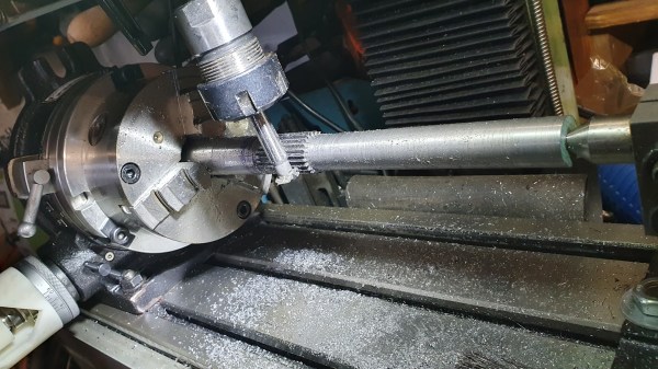
An RP2040 provided the brains of the project, while a NEMA 23 stepper provides the brawn. [Tony] whipped up a quick PCB and 3D printed a case for the microcontroller, a stepper driver, an LCD display, and a few buttons. He 3D printed an adapter and a shaft coupler to mount the stepper motor to a rotary table. From there it was just a matter of coming up with a bit of code to run everything.

There’s a brief video in [Tony]’s blog post that shows Rotary Table Buddy in action, indexing to the next position after cutting one of the 23 splines. He says it took about ten minutes to cut each spline using this setup, which probably makes to total cutting time far less than the amount of time invested in the tool. But that’s hardly the point, and besides, now he’s set up for all kinds of machining operations in the future.

And we sure hope we hear about the EMF Camp build, too.

Upgrade A 3D Printed CNC Milling Machine By Using It

One of the original ideas behind the RepRap project was for the machines to create their own upgrades. That philosophy is shining brightly in [Ivan Miranda] CNC milling machine project, which has been used to upgrade its aluminum and 3D printed frame components to steel.

For precision machining on hard metal, machine rigidity is of utmost importance. [Ivan]’s original CNC mill made extensive use of lightweight aluminum extrusions with 3D printed fittings. The machine worked, but the lack of rigidity was visible in the surface quality of the machine parts. The latest upgrade included a completely new frame from welded steel tubing and heavy aluminum mounting plates. The original machine was used to slowly machine slots in the steel tubes to retain the adjustability of the Z-axis. Some of the 3D printed motor mounts remained, so in the second video after the break [Ivan] used the newly upgraded machine to mill some aluminum replacements.

While this machine might not be perfect, we have to respect [Ivan]’s willingness to toss himself in at the deep end and show all failures and lessons learned the hard way. This project was clearly used as an opportunity to improve his welding and machining skills. His fabrication skills have come a long way from mainly 3D printed projects like the giant tracked tank and screw tank.

Continue reading “Upgrade A 3D Printed CNC Milling Machine By Using It”

Scrapyard Milling Machine Gets Work Done On A Budget

Which to buy first, a lathe or a mill? It’s a tough question for the aspiring home machinist with limited funds to spend on machine tools, but of course the correct answer is a lathe. With a lathe, we are told, all other machine tools can be built, including a milling machine. Granted that might be a slight  exaggeration, but [Maximum DIY] was still able to use his budget-blowing lathe to make a decent milling machine mostly from scrap.

Details are a bit sparse in the forum post, but there’s enough there and in the video after the break to be mightily impressed with the build. Unlike many DIY mills that are basically modified drill presses, [Maximum DIY] started with things like a scrapped bench grinder pedestal and surplus steel tubing. The spindle motor is from a paint sprayer and the Z-axis power feed is a treadmill incline motor. The compound table was a little too hard to make, so the purchased table was fitted with windshield wiper motor power feeds.

Therein lies perhaps the most clever hack in this build: the use of a plain old deep 19mm socket as a clutch for the power feeds. The 12-point socket slides on the square shaft of the wiper motor to engage the drive screw for the compound table – simple and bulletproof.

To be sure, the finished mill is far from perfect. It looks like it needs more mass to quell vibration, and those open drive pulleys are a little nerve wracking. But it seems to work well, and really, any mill is better than no mill. Of course, if you’re flush with cash and want to buy a mill instead of making one, this buyer’s guide should help.

Continue reading “Scrapyard Milling Machine Gets Work Done On A Budget”

CNC Your Own PCBs With A 3D Printed Mill

Yes, you can whip up a design for a printed circuit board, send it out to one of the many fab houses, and receive a finished, completed board in a week or two. There are quick-turn assembly houses that will manufacture a circuit board and populate it for you. But sometimes you need a board now, and that’s when we get into home PCB fabrication. You can do this with either etching or milling, but [Renzo] has a great solution. He built a 3D printed milling machine that will make a printed circuit board.

The design of this tiny micro mill is based on a handheld rotary tool, also called a Dremel, but that’s like Kleenex, so just buy a Proxxon. This mill is designed with 3D printed T-track and constructed with linear bearings on smooth rods with standard NEMA 17 stepper motors and herringbone gears for little to no backlash. There is quite a bit going on here, but lucky for us [Renzo] has a video tutorial of the entire build process available for viewing below.

We’ve previously seen some of [Renzo]’s previous efforts in homemade PCB fabrication, up to and including applying green soldermask with the help of Fritzing. This is good, very good, and the only thing that really separates this from manufactured PCBs is the lack of plated through holes. That’s just a bit of graphite and electroplating away, and we’re looking forward to [Renzo]’s further adventures in making PCBs at home.

Continue reading “CNC Your Own PCBs With A 3D Printed Mill”

Hack Chat: The Home Machine Shop With Quinn Dunki

Join us Wednesday at noon Pacific time for the Home Machine Shop Hack Chat!

Even if you haven’t been here for very long, you’ll probably recognize Quinn Dunki as Hackaday’s resident consulting machinist. Quinn recently did a great series of articles on the “King of Machine Tools”, the lathe, covering everything from the history of precision machine tools to making your first chips. She’s documented the entire process of procuring and setting up a new lathe, pointing out all the potential pitfalls the budding home machinist may face. You can get a much deeper dive into her machining adventures on her YouTube channel, Blondihacks.

Flinging hot metal chips around is hardly all Quinn has accomplished, though. Long before her foray into machine tools, there was Veronica, a scratch-built 6502 machine Quinn created as an homage to the machines that launched her into a life of writing software. We’ve featured Veronica on our pages a couple of times, and she’s always made quite a hit.

Please join us for this Hack Chat, where we’ll discuss:

  • How developing software and machining are alike, and how they differ;
  • How social networks have changed the perception of machining;
  • Best practices for getting started in machining; and
  • Are there any new machine tool purchases in the pipeline?

You are, of course, encouraged to add your own questions to the discussion. You can do that by leaving a comment on the Home Machine Shop Hack Chat and we’ll put that in the queue for the Hack Chat discussion.

join-hack-chatOur Hack Chats are live community events on the Hackaday.io Hack Chat group messaging. This week we’ll be sitting down on Wednesday, March 20, at noon, Pacific time. If time zones have got you down, we have a handy time zone converter.

Click that speech bubble to the right, and you’ll be taken directly to the Hack Chat group on Hackaday.io. You don’t have to wait until Wednesday; join whenever you want and you can see what the community is talking about.

Air Wrench Becomes A Milling Machine Power Drawbar

We sometimes wonder if designers ever actually use their own products, or even put them through some sort of human-factors testing before putting them on the market. Consider the mechanism that secures toolholders to the spindle of a milling machine: the drawbar. Some mills require you to lock the spindle with a spanner wrench, loosen the drawbar with another wrench, and catch the released collet and tool with – what exactly?

Unwilling to have the surgical modifications that would qualify him for the Galactic Presidency, [Physics Anonymous] chose instead to modify his mill with a power drawbar. The parts are cheap and easily available, with the power coming from a small butterfly-style pneumatic wrench. The drawbar on his mill has a nearly 3/8″ square drive – we’d guess it’s really 10 mm – which almost matches up with the 3/8″ drive on the air wrench, so he whipped up a female-to-female adapter from a couple of socket adapters. The wrench mounts to a cover above the drawbar in a 3D-printed holster. Pay close attention to the video below where he goes through the Fusion 360 design; we were intrigued by the way he imported three orthogonal photos on the wrench to design the holster around. That’s a tip to file away for a rainy day.

This is a great modification to a low-cost milling machine. If you’re in the process of buying machine tools, you should really check out our handy buyer’s guides for both milling machines and lathes. It’ll let you know what features to look out for, and which you’ll have to add later.

Continue reading “Air Wrench Becomes A Milling Machine Power Drawbar”

Rolling Out A Slick Rotary Phase Converter

Home machinists can often find great deals on used industrial equipment, and many a South Bend lathe or Bridgeport milling machine has followed someone home. Then comes the moment to plug it in, and the new owner discovers that the three-phase plug needed to power the new beast is nowhere to be found in the shop. Thus commences the weeping and the gnashing of teeth.

Luckily, [Handmade Extreme] is ahead of the curve in terms of shop power, and built a rotary phase converter to power his machines. Industry generally runs on three-phase AC systems, mainly because three-phase electric motors are so much more efficient and compact than the equivalent single-phase motor. But residential electrical service is either split-phase or, in the UK where [Handmade Extreme] is based, single phase. A rotary phase converter is an electromechanical device that can generate the missing phases – in essence a three-phase motor that can run on one winding and generate the missing phases across the other windings. It needs some supporting control circuitry to do so, such as timers and contactors to switch the winding connections once the motor starts, plus capacitors for motor starting and for balancing the voltage across the phases. The control gear is DIN-rail mounted and neatly wired to a smart-looking control panel. Everything is housed in a sturdy enclosure that’s big enough to serve as a mobile tool cart. It’s a really nice job – watch the whole build in the video below.

If you’re interested in power distribution, we’ve got a primer that covers the basics. And if you’re in the market for machine tools, [Quinn]’s machine tool buyer’s guide will let you decide if a three-phase machine is worth the extra effort.

Continue reading “Rolling Out A Slick Rotary Phase Converter”