Lightning is one of the great forces of nature. The huge releases of electricity release detectable electromagnetic emissions, as you might expect. The team at the [LVL1 Hackerspace] put together a lightning detector of their own; one which keeps count of the number of discharges in the atmosphere.
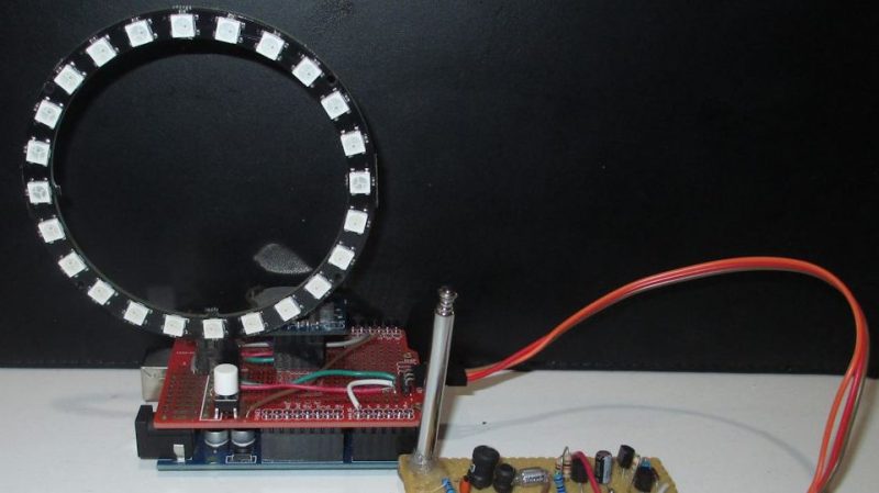
The device consists of a typical tank circuit tuned to 300kHz, paired with a small telescopic antenna. Lightning strikes in the area induce an oscillation in the circuit which is amplified and then detected by an Arduino. The Arduino measures the voltage of the pulse, which is proportional to the magnitude of the signal detected. A ring of Neopixel LEDs are then switched on relative to the intensity of the signal. Additionally, when not actively detecting strikes, the Arduino instead uses the LEDs to display the current time and a binary count of the number of strikes detected since it has been running.
It’s a simple build, and one that would serve as a great introduction into the world of addressable LEDs and environmental monitoring. If you’d like to go about it another way, you can detect lightning with an SDR, too!


Such a device would have been interesting a couple weeks ago when we had a storm roll through here, north of Denver, CO, that spent about an hour with discharges about 3-4 times per minute. New experience for a new resident.
The article inspires me to revisit a similar circuit I built and used to fire my DSLR in response to discarges. Sadly, that board, along with everything else in the home, was lost in a CA wildfire this time last year… Lots of stuff to replace!
I’ve had good success working with designs I found on http://techlib.com/electronics/lightningnew.htm
Looking through the schematic with R5 crossed out, it looks like the reason you couldn’t use the potentiometer there is that it created a voltage divider with R9 ensuring that transistor Q2 was always turned on.
To my eye, it looks like D2 might be unnecessary, and I think you can remove it from the circuit without negative effect.
Lightning detection has always interested me, so I’m happy to see information on this kind of project.
However, the schematic on the OP’s page is likely to cause a lot of frustration on the part of anyone trying to replicate it. Why?
R2, R3, C2, and the base of Q1 meet at a cross-shaped intersection. Is that supposed to be a four-way connection or two orthoganal wires crossing?
Well, if you know something about amplifiers, you will interpret R2 and R3 as bias/feedback resistors for Q1, and C2 as a DC blocking cap. That external knowledge would lead you to conclude that all four components are probably meant to join here.
So what’s the big deal then? OK, now look at the wiring at the collector of Q2. Here is another, identical, cross-shaped intersection involving Q2, R7, and C4. Only here, the intersection -must- be a cross-over. If you treat it the same as the first intersection, then Q2 would be short-circuited.
My complaint is that the same symbology is used to mean two opposite things, in a single schematic!
Crosses on schematics have always been a source of ambiguity. Some people use a black connector dot to differentiate a 4-way connection from a crossover. In years past the cross was understood to mean 4-way connection and cross-overs were denoted through the addition of little arch-shaped jumps. Unfortunately, dots sometimes get lost in low resolution images and arch-overs at intersections have fallen from favor.
I therefore recommend this: ALWAYS use a simple orthoganal cross to denote a cross-over condition.
If you mean to depict the connection of four components, then offset one of the arms at the intersection so that it is NOT a cross.
This approach is unconditionally unambigous, even at low resolution. Developing the practice to do electronic schematics this way will also prevent ambiguity from resulting in unintentional opens or shorts in your pcbs.
Final Schematic of Detector updated to reduce confusion on connections vs jump-over. Original schematic and source schematics left unchanged. Connections indicated by “DOTS” of appropriate size for image resolution and “ARCHES” for non-connections.
Thanks! I’ve played with the first part of the schematic (up until R3) and hooked an oscilloscope to R3 to see what it would look like during a thunderstorm. It’s a lot of fun watching the strikes appear on the plot. I used a longer antenna about 60-70cm. I’ve found I could detect lightning about 20-25km away, with the trigger threshold at about 250mV. Not even a battery was needed, it would produce voltages of between 500mV to about 12V peak to peak when the storm was very close.
I tested it with a lighter with an piezo element that produces an electric spark before the storm to see if it even registers anything, and it totally worked.
Looking at the picture, one might assume the lightning detector indicated direction. Some aircraft ADF’s could be used to detect lighting and direction (somewhat). The benefit of a lot more circuitry and ESA.