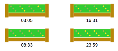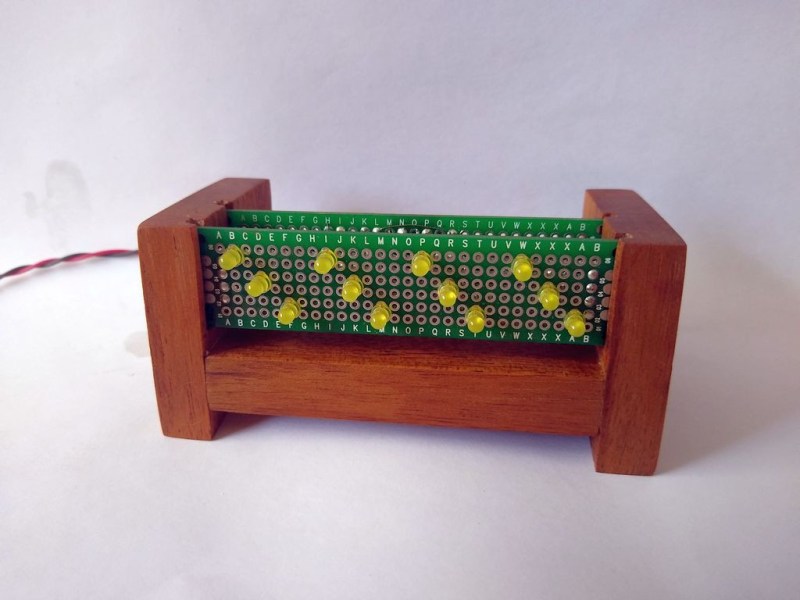
Over on Hackaday.io, [danjovic] presents clOCkTAL, a simple LED clock for those of us who struggle with the very concept of making it easy to read the time. Move aside binary clocks, you’re easy, let’s talk binary coded octal. Yes, it is a thing. We’ll leave it to [danjovic] to describe how to read the time from it:
Do not try to do the math using 6 bits. The trick to read this clock is to read every 3-bit digit in binary and multiply the MSBs by 8 before summing to the LSBs.
Simple. If you’re awake enough, that is. Anyway, we’re a big fan of the stripped-down raw build method using perf board, and scrap wood. No details hidden here. The circuit is straightforward, being based on a minimal configuration needed to drive the PIC16F688 and a handful of LEDs arranged in a 3×4 matrix.
An interesting detail is the use of Bresenham’s Algorithm to derive the one event-per-second needed to keep track of time. And no, this isn’t the more famous Bresenham’s line algorithm you may be more familiar with, it’s much simpler, but does work on the same principle of replacing expensive arithmetic division operations with incremental errors. The original Bresenham’s Algorithm was devised for using with X-Y plotters, which had limited resolution, and was intended to allow movements that were in an imperfect ratio to that resolution. It was developed into a method for approximating lines, then extended to cover circles, ellipses and other types of drawables.
Bresenham’s Algorithm allows you to create the event you want, with any period from any oscillator frequency, and this is very useful indeed. Now obviously you don’t get something for nothing, and the downside is periodic jitter, but at least it is deterministic. The way it works is to alternate the period being counted between two power-of-two division ratios (or something easily created from that) such that the average period is what you want. Cycle-to-cycle there is an error, but overall these errors do not accumulate, and we get the desired average period. The example given in [Roman Black]’s description is to alternate 16 cycles and 24 cycles to get an average of 20 cycles.
The software side of things can be inspected by heading over to the clOCkTAL GitHub which makes use of the Small Device C Compiler which has support for a fair few devices, in case dear readers, you had not yet come across it.
The video shows the clock being put through a simple test demonstrating the LED dimming in response to ambient light. All-in-all a pretty simple and effective build.


Ah man! I overslept again! it’s almost 11100101 !
drwxr-xr-x … if you used *nix for a while you can probably read this clock easier than their fully binary counterparts
Hey, great idea for a 12 hour clock. The real Unix time!
“Binary coded octal”… but this is just binary, right? It’s just arranging the bits in groups of three. If it were groups of four I could call it “binary coded hexadecimal”. I don’t see the difficulty.
That is right. Both octal and hexadecimal are just convenient ways of reading and entering binary information that are slightly easier for humans than binary. It’s only really octal if you are displaying the digits as 0..7. Calling it “binary coded octal” is a little silly, really, since octal is just a trivial encoding of binary. So it’s binary-coded-binary.
“Do not try to do the math using 6 bits. The trick to read this clock is to read every 3-bit digit in binary and multiply the MSBs by 8 before summing to the LSBs.”
??? This seems like nonsense. ???
Can someone show me an example where a 6-bit binary value is different from a 3-bit value times 8 plus another three-bit value?
I don’t think he meat that it is different, just that it is easier. Most people can do 3 bits without problems, but six bit is a little more tricky. That’s why a lot of languages support octal as well.
Yes, but they represent them as Arabic numerals 0 through 7, not just on or off LEDs. It’s not one whit easier. A number of 1950s – 70s computer makers who made computers with programming/maintenance front panels used binary, but color-coded the panel into groups of three or four bits, depending on the preference of the particular manufacturer (e.g., DEC used 3-bit groups everywhere, while Data General used 4-bit groups). But they did not call these panels hexadecimal or octal. They called them what they were: binary.
I think you’ve buried the lead, here. The clock, yawn, is okay as binary clocks go, but what’s news to me is the mention of SDCC, a C compiler specifically setup for a number of microcontrollers and small microprocessors. I’m hoping it’s better optimized for small systems than GCC seems to be.
Bless your optimism…
“….for those of us who struggle with the very concept of making it easy to read the time.”
Ha! The twelve LEDs could have instead just been put into one group to represent the time in a single 12-bit word. For example 23:59 (2359 decimal) would be: 100100110111.
Thanks Dave, i too found something new & interesting in you highlighting Bresenham’s Algorithm
“Do not try to do the math using 6 bits. The trick to read this clock is to read every 3-bit digit in binary and multiply the MSBs by 8 before summing to the LSBs.”
Ow, my head.
The left LED is useless for 24 hours day…
I just now realized this. I kinda want to build this so I’ll probably omit the leftmost LED. I don’t care about the aesthetic more than I care about function.
The other question I’m thinking about is how do I make it a real 12 hour clock? I can’t stand 24 hour clocks for regular use. I took a look at the source code but I’m unsure if I should just define the hours as 12 versus 24. It seems that’s the proper way to go about it.
Use that left led for the AM/PM.
> The way it works is to alternate the period being counted between two power-of-two division ratios (or something easily created from that) such that the average period is what you want. Cycle-to-cycle there is an error, but overall these errors do not accumulate, and we get the desired average period. The example given in [Roman Black]’s description is to alternate 16 cycles and 24 cycles to get an average of 20 cycles.
24 is not a power-of-two. The Bresenham algorithm is the same as the Bresenham line-drawing algorithm. Roman Black’s trick is that to make the math work in integer math is to accumulate the bresenham line-drawing sum in fractional pixels. The power-of-two is a red herring. It could be 1000 micropixels, or the convenient 256 counts in a Timer 0 overflow or whatever you like. The 16 versus 24 to get 20 example is more understandable as if you can only generate an event every 8 cycles, you can get a jittery but perfect 20 cycle period using the bresenham algorithm and it will switch between 16 and 24 cycles. Same for producing a 17, 18, 19, 21, 22, 23 or even a 17.314159-cycle period– the bresenham algorithm keeps track of the fractions to make the ratio correct.