Like so many of us, [aforsberg] found themselves fascinated with the WOPR computer from WarGames — something about all those blinking LEDs must speak to nerds on some subconscious level. But rather than admire the light show from afar, they decided to recreate it at a scale suitable for a 1U server rack.
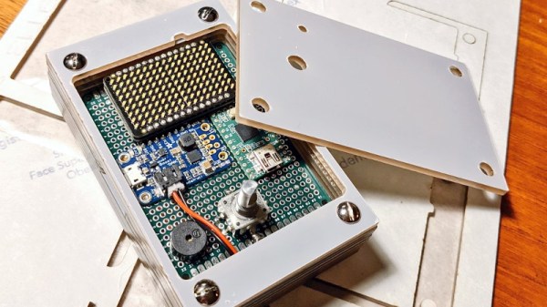
So what goes into this WOPR display? In this case, the recipe simply calls for three MAX7219 dot matrix LED modules and a Raspberry Pi Pico, although you could swap that out for your favorite microcontroller if you wish. You should probably stick with something that at least runs MicroPython though, or else you won’t be able to use the included Python code to mimic the light patterns seen in the film.
What we like most about this project is how simple and inexpensive it is to recreate. There’s no custom PCB, and all the parts are mass produced enough that the economies of scale have made them comically cheap. Even at Amazon prices, you’re looking at around $50 USD in parts, and quite a bit less if you’ve got the patience to order everything through AliExpress.
Critics will note that, in its current state, this display just shows gibberish (admittedly stylish gibberish, but still). But as we’ve seen with similar projects, that’s simply a matter of software.