ClOCkTAL: For When Reading A Clock Is Just Too Easy

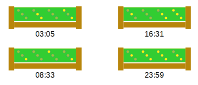
Over on Hackaday.io, [danjovic] presents clOCkTAL, a simple LED clock for those of us who struggle with the very concept of making it easy to read the time. Move aside binary clocks, you’re easy, let’s talk binary coded octal. Yes, it is a thing. We’ll leave it to [danjovic] to describe how to read the time from it:

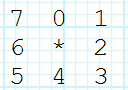
Do not try to do the math using 6 bits. The trick to read this clock is to read every 3-bit digit in binary and multiply the MSBs by 8 before summing to the LSBs.

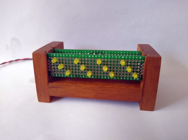
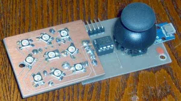
Simple. If you’re awake enough, that is. Anyway, we’re a big fan of the stripped-down raw build method using perf board, and scrap wood. No details hidden here. The circuit is straightforward, being based on a minimal configuration needed to drive the PIC16F688 and a handful of LEDs arranged in a 3×4 matrix.

An interesting detail is the use of Bresenham’s Algorithm to derive the one event-per-second needed to keep track of time. And no, this isn’t the more famous Bresenham’s line algorithm you may be more familiar with, it’s much simpler, but does work on the same principle of replacing expensive arithmetic division operations with incremental errors. The original Bresenham’s Algorithm was devised for using with X-Y plotters, which had limited resolution, and was intended to allow movements that were in an imperfect ratio to that resolution. It was developed into a method for approximating lines, then extended to cover circles, ellipses and other types of drawables.

Continue reading “ClOCkTAL: For When Reading A Clock Is Just Too Easy”

Voltage Monitor Relay Is More Than Meets The Eye

Automotive components that have a hidden secondary function are usually limited to cartoons and Michael Bay movies, but this project that [Jesus Echavarria] created for a client is a perhaps as close as we’re likely to get in the near future. The final product certainly looks like a standard automotive relay, but a peek inside the 3D printed case reveals a surprisingly complex little device. It’s still technically a relay, but it uses a PIC microcontroller to decide when it should activate.

[Jesus] was given the task of creating a device that would fit into the relay box of a vehicle, and serve as a battery monitor to fire off at different voltage set points. The client also wanted the ability to configure such things as how long the device would wait before enabling and disabling the alarms once the voltage threshold has been passed. After showing the client an oversize prototype using a PIC16F88 and switching regulator, he got the OK to move on to a smaller and more cost-effective version.

The final hardware makes use of a 78M05 500 mA linear regulator, a PIC16F1824 microcontroller, and a pair of AQY211EH solid state relays. The standard five pin layout used for automotive relays allows the monitor to get power from the vehicle’s battery while providing two output channels that can be switched on and off from the microcontroller. [Jesus] says an agreement with the client prevents him from sharing some elements of the project (like the firmware source code), but he gives enough information that it shouldn’t be too hard to spin up your own version.

With the addition of something like an ESP8266, this could be an easy way to retrofit an older vehicle with “smart” features. As an example, it could potentially allow for controlling the car’s headlights and horn over Wi-Fi. Or you could hack together a theft deterrent system that refuses to power on the starter or fuel pump unless your smartphone enables the relay first.

Pic16maze secret maze game

PIC16Maze Upgrades Secret Maze Game

We really like it when a reader is inspired by something they see on Hackaday, build on it, and let us know so we can pass it on. In this case, [Vegipete] made a secret maze game using a minimal number of parts and some neat software trickery.

It’s built around an 8-pin PIC16F18313 microcontroller, uses a joystick for input, and nine WS2812 LEDs to display the player and the surrounding maze walls. His inspiration was [David Johnson-Davies’] minimalist secret maze game built around the 8-pin ATTiny85. In that one, [David] cleverly used charlieplexing to get four pins to control four LEDs and four pushbuttons. [Vegipete’s] use of the WS2812 LEDs allowed him to control the LEDs with just one pin, and also get color while using three pins for the joystick and its button. He may use another pin in the future for sound and vibration.

He goes into some detail on the WS2812 protocol, how communication is done with the LEDs using just one pin and different pulse-lengths to represent 0 and 1. We’ll leave you to see his post for more depth but basically, he introduces a module on the PIC called the Configurable Logic Cell (CLC) which makes this easy and frees up processor cycles for the user’s code to do other things.

Secret maze wall bitsHis source code is available on request but he does detail a neat software trick he uses for rotating the view. It may be confusing for some but as you move through the maze, your viewpoint rotates so that up is always the direction you’re facing. Luckily, the walls surrounding the user can be represented using 8-bits, four for east, west, north, and south, and four more for the corners. The maze is stored as a bitmap and from it, 8-bit values are extracted for the current position, each bit representing a wall around the position. To rotate the walls to match the user’s current orientation, the bits are simply shifted as needed. Then they’re shifted out to set each LED. Check it out in the video below.

It works very well despite the minimal interface and part count.

Continue reading “PIC16Maze Upgrades Secret Maze Game”

Microchip Launches New Family Of PICs

Over the last few years, we’ve seen projects and products slowly move from 8-bit microcontrollers to more powerful ARM microcontrollers. The reason for this is simple — if you want to do more stuff, like an Internet-connected toaster, you need more bits, more Flash, and more processing power. This doesn’t mean 8-bit microcontrollers are dead, though. Eight bit micros are still going strong, and this week Microchip announced their latest family of 8-bit microcontrollers.

The PIC16F15386 family of microcontrollers is Microchip’s latest addition to their portfolio of 8-bit chips. This family of microcontrollers is Microchip’s ‘everything and the kitchen sink’ 8-bit offering. Other families of PICs have included features such as a complementary waveform generator, numerically controlled oscillator, a configurable logic controller, power saving functionality and the extreme low power features, but never before in one piece of silicon.

This feature-packed 8-bit includes a few new tricks not seen before in previous Microchip offerings. Of note are power management features (IDLE and DOZE modes), and a Device Information Area on the chip that contains factory-calibrated data (ADC voltage calibration and a fixed voltage reference) and an ID unique to each individual chip.

As you would expect from a new family of PICs, the 16F15386 is compatible with the MPLAB Xpress IDE and the MPLAB Code Configurator, a graphical programming environment. The products in the family range from 8-pin packages (including DIP!) with 3.5kB of program Flash to 48-pin QFPs with 28kB of program Flash. The goal for Microchip is to provide a wide offering, allowing designers to expand their builds without having to change microcontroller families.

All of these chips can be sampled now, although the lower pin count devices won’t be available through normal means until next month.

PhilRobokit Anito Is Not An Arduino

A few people over at the Philippine hackerspace PhilRobotics a PIC-based dev board that takes a lot of cues from ‘the microcontroller board everyone loves to hate,’ the Arduino.

There are a few differences between the PIC16F877a used in the Anito and the ATMega328 used in the Arduino: The PIC has a little less than half the Flash memory of the ‘Mega and less RAM, but has a slightly higher clock rate. It would have been nice to have a dev board with Arduino style headers powered by one of those new PIC32MX chips, if only because of a few really, really awesome projects we’ve seen. We’ll take whatever we can get, though, even if it provides a little more ammo for the PIC/AVR holy war.

One really interesting aspect of the Anito is the IDE. Written in Python, the PhilRoboKit IDE has all the features of everyone’s favorite IDE that is written in Wiring, plus a few extra features: autocomplete is a huge bonus, as is the ability to upload programs over Pickit2 ISP header. The IDE is available for Windows and Linux (no Mac port yet), and should be enough to get you off the ground in the PIC dev world.

Digital Magic 8 Ball

[sjm4306] had a small Magic 8-Ball key chain as a kid. The fluid in this key chain eventually dried up, and if [sjm] is anything like us the 20-sided die is now lost to the sands of time or at the very least hidden in a box in the basement. After remembering the old Magic 8-Ball one day, [sjm] decided to build a digital version of everyone’s favorite bewitched billiard ball.

The digital magic 8-ball uses a PIC16f886; more than enough to hold the twenty possible replies from a real magic 8-ball. The display is a tin 3 cm OLED which surprisingly emulates the ‘icosahedron with raised letters floating in purple liquid’ aesthetic very well.

Right now, this is just a breadboard prototype – there isn’t an accelerometer or tilt switch in the build yet, so shaking the project does absolutely nothing. [sjm] may add that functionality later by turning his project into a watch, key chain, or installing it in a real Magic 8-Ball case.

Chrono-tomic Shield Helps Your Arduino Keep Perfect Time

chronotomic-arduino-shield

[Josh] and his lab partner [Eric] needed a final project for their Embedded Systems Design class, and thought that designing an Arduino shield would be a cool idea. They noticed that there are plenty of ways to get an Arduino to keep time, though none that they knew of utilized WWVB (Atomic Time) signals directly.

The Chrono-tomic Arduino shield uses a C-MAX radio to demodulate the WWVB signal, demodulating it and passing it along to a PIC16F1824 microcontroller. The PIC decodes the data frame and verifies it is valid, sending the time to an MCP79410N real-time clock module.

We can hear the “Yo dawg I herd you like microcontrollers so I put a microcontroller on your microcontroller shield” jokes already, but the pair says that they offloaded the time processing to the PIC in order to let the Arduino focus on whatever tasks it has been delegated. The Arduino code merely needs to request the time from the RTC whenever it is required, rather than deal with the decoding itself.

Is it overkill? Perhaps – though we think it heavily depends on your application and configuration. We can certainly conjure up situations where it would be useful.