If you’ve done anything with modern lighting effects, you’ve probably heard of DMX, also known as DMX512. Ever wonder what’s really happening under the hood? If so, then you should have a look at [EEForEveryone’s] video on the topic, which you can see below.
At the core, the DMX512 uses RS485, but adds software layers and features. The video uses the OSI model to show how the system works.
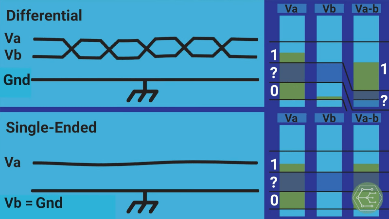
Of course, RS485 is just a physical layer like a serial port. The DMX standard defines an actual protocol. If you haven’t used RS485 before, there’s a good explanation of differential signaling and why it is important when you have high data rates or long signal paths. There’s also a discussion of alternate physical layers such as networked DMX512 and wireless DMX.
The 512 part of the name refers to the maximum number of devices on the bus. However, with the networked variation you can use a single Ethernet cable to connect up to 400 DMX busses to one network device. That’s quite a few DMX channels. Each channel is a byte, so a typical RGB LED, for example, consumes three channels.
We’ve seen DMX in a backpack. If you do it right, the DMX can not only react to music, it can be part of the instrument that creates it, too.


The part that continues to confuse me when using rs485, modbus rtu or dmx… Is the gnd signal drawn in the differential signal drawing needed or not?
All of these uses of rs485 are typically used for long mulridrop busses, often in noisy environments. In my opinion it is a bad thing to connect the gnd of the devices. The differential signal is perfectly capable to transmit it’s data without needing a ground reference. Connecting the gnd signal will most likely cause ground loops when the devices are grounded locally..
This is how I was taught at school. However I find that using these signals on short drops in hobby projects simply won’t work without the gnd connected..
If not isolated (magnetics for example) then you will want the gnd. Otherwise if gnd potentials are different at different endpoints, signal voltage levels could blow up chips…
Within the same room? Along a chain powered from the same panel? Probably won’t need it.
+1 Connecting the ground to the shield increase also the parassitic capacitance of the 485 bus, decreasing accordingly the maximum lenght of the cable you can use, even if you connect the ground only on one side of the cable in order to avoid gnd loops.
RS485 has an official common mode range between -7 and +12 volts. ( so that’s 7 volts outside GND and +5V power supply)
If you get outside of those limits you may start pulling current from the RS485 lines. You also have to keep these limits (or something close) in mind if you want to harden your RS485, for example by adding extra TVS diodes.
If there is no GND wire, then the common mode levels are “undefined”, and if you accidentally get out of the common range then your RS485 drivers may start pulling current, which distorts the RS485 signals and may damage your IC’s.
From an old video from Mikeselectricstuff I got the tip to add TVS diodes to make RS485 more robust, but also add PPTC fuses on each node. This keeps the hardware intact if for example the RS485 lines are accidentally connected to +24Vdc (or -24Vdc) due to a wiring fault. The TVS diodes protect the RS485 drivers against spikes, and the PPTC’s protect the TVS diodes against DC overload.
For a more general paper I highly recommend:
https://html.duckduckgo.com/html?q=Ten+ways+to+bulletproof+RS485
I am a bit confused by this Hackaday article, and the video it mentions.
It does not explain DMX512 very well. I never used it myself. As far as I can remember the data format is a break, followed by (upto) 512 bytes of data in standard uart 8n1 format.
RS485 does not define a coding for the bits, and this is mentioned only very briefly.
I make use of this by soldering an RS-485 driver to an S/PDIF output, adding a bunch of CAT-5 cable and using RS485 receivers on the other end to distribute the same audio to different rooms. It’s very simple and robust and you never have problems with audio out of sync. (Unless you add heavy DSP processing on some of the endpoints, which add additional delays)
Another part that is not very clear from the video is that the common mode range of RS485 is defined also for negative input voltages. I use RS485 for a small microcontroller network, in which both power and data is sent through an CAT-5 cable. Power (24Vdc) is injected somewhere in the middle, and CAT-5 can handle up to about 1A. but long cables loose a few volts at that current. That means that the GND level for a node at the end of the cable is lifted, but the RS485 pair stays at the same level, and therefore it dips below the GND level of nodes at the end of the cable.
And vise versa. If a node at the end of the cable sends data, then the data will be above +5V in the middle of the cable.
Same as with CAN, use ground if devices on the bus are powered from different sources. Otherwise no need to have a common ground.
It is really, really unwise to skip the ground. Don’t do it. 9 times out of ten short runs will work just fine if you do skip it but then you will find a problem – and it is always in the most inconvenient, embarrassing and inaccessible location. DMX was developed to be robust and fast and sent over balanced, grounded and shielded XLR connectors – skipping the ground is removing a part of that robust design. Do it right and you have a bullet proof system. DO it wrong at your peril. Also DMX is sometimes peculiar in that a noisy line will not simply fail out lie some other protocols, instead it will write garbage to your control lines. Sometimes only on a Tuesday afternoon when that guy with a vontage Nokia phone walks past. Beware. Connect those grounds.
The ground is there to shield the twisted pair cable from EMI, not as a signal reference. The signal is effectively in a Faraday cage, helping to prevent EMI from inducing noise onto the wires. Although both wires will pick up the same noise (such that it should be rejected as common-mode), enough noise will exceed the CMRR and cause problems.
IIRC, the RS485 standard requires shields connected at both ends. Unconnected or singly connected shields can act as antennas and pick up all sorts of EMI.
If ground differential is a problem, galvanic isolation of the link is the correct solution. That should eliminate the ground current because there’s no return path.
Another thing to consider with differential signals is DC balance. In the DMX512 case, and standard UART cases, the data is sent using Non-Return-to-Zero (NRZ) coding. If you are to transmit a continuous signal that consists of more ‘0’s than ‘1’s, the average value of the voltage on both wires will tend to drift towards the ‘0’ value. A return path can allow that current to flow back to the source, and help with DC balance. Note that all the other arguments about ground paths still apply. For really high speed differential links that carry data, it is advantageous to encode the data in some kind of Return to Zero (RZ), Manchester encoding, or use something like alternating phase. CAN bus chooses a kind of RZ encoding, where the line idles at about half voltage, and when a dominant signal is sent, you equal excursions on both the positive and negative lines, this gives an average DC value of half way to the supply rail. Many systems also use coding like 8B/10B where the codes are chosen to have minimal DC offset, furthermore, a second disparity set of codes is used in alternating fashion to cancel out any remaining DC offset. SONET networks use this kind of coding.
Nice story, but DC balance is completely irrelevant for RS485.
First, it’s a differential signal, so the two wires balance each other out.
Second, RS485 has termination resistors that happily eat a bit of DC.
My personal experience is that DMX is slow enough and robust enough that you can get away with running it down just about any wire. The shield helps a lot when there is heavy electrical noise like motors or strobes, etc. Correct termination at the end of line helps a lot…those system running RDM need termination on both sides of the line because you now have a multi-master situation.
Anyway, grounding:
From the ANSI E1.11-2008(R2018):
4.5 Data link common and grounding topologies
Various portions of clause 5 and Annex A deal with shield-to-earth ground topologies. In all cases there is a low
impedance connection between data link common pin or contact of the DMX512 port and signal common of the
EIA-485-A driver or receiver circuitry.
4.6 Preferred method of earth grounding data link common
DMX512 systems should make use of earth ground referenced transmitting devices and isolated receiving
devices. This approach provides for a single point solid ground/chassis connection at the source, and allows for
variations in building ground potentials between transmitting and receiving devices. This is to ensure that
interoperability of equipment is achieved in situations that might otherwise exceed the Common Mode limitations
of EIA-485-A. See EIA-485-A clause 4.3.1. Other approaches are covered in Annex A.
And I think I have seen this used maybe once:
10.4 Ground / Isolation marking
All DMX512 ports shall indicate the relationship between Data Link Common and earth ground. The allowed
grounding topologies are shown in table 9.
Table 9 – Ground / Isolation marking
Function of DMX512 port Defining Clause / Figure Comment Approved Marking
Transmitter clause 5.4 / fig 1 Ground Referenced no mark required, recommended mark
Transmitter clause A1 / fig A1 Isolated (See Annex A) ISO or ISOLATED
Transmitter clause A4 / fig A4 Floating (See Annex A) FLT or FLOAT or FLOATING
Receiver clause A2 / fig A2 Non-Isolated,100 ohm 2 Watt resistor NON-ISO or NON-ISOLATED
Receiver clause A3 / fig A3 Grounded – concession per clause A3
Receiver clause 5.7 / fig 3 Isolated no mark required; ISO or ISOLATED
Receiver clause A4 / fig A4 Floating FLT or FLOAT or FLOATING
Note: Although no mark is required of Ground Referenced transmitters or Isolated
receivers, it is highly recommended that such markings appear on the product
I see the usual level of confusion reigns in the question of grounding differential interfaces. RS485 is really just an extension of the original RS422 hardware interface that provides common mode capability at both the receiver AND driver rather than just at the receiver in the RS422 case. They really are pseudo-differential interfaces rather than being truly differential since the diffentiality is in the measured V(+)-GND and V(-)-GND terms. So providing a common driver-receiver ground reference is in the frame.
At the data rates you guys are using the impact of TVS protection on signal quality is going to be negligible. In any case unless I was designing for an industrial environment or one where local supplies were probably drawn from different AC line phases I’m not sure I’d bother.
I remember looking at some power integrity issues that a client was having in a very large computer system. I came across a pseudo-differential receiver whose ground reference was being hammered by the inrush currents from an adjacent POL regulator. The differential input voltage was sagging to a few tens of millivolts at times but the output was still fine with surprisingly little jitter. We cleaned up the decoupling on the POL and the potential problem went away. So yes, pseudo-differentialsignalling works ok if you take a little care