Hacker Dictionary: RS-485 Will Go The Distance

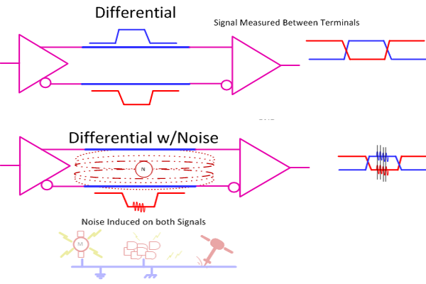
RS485 is a communication standard that should be part of the advanced hardware hacker’s arsenal; it’s not commonly encountered, but powerful exactly when you need it. It’s a physical layer interface for wired communications that uses a single differential pair for noise immunity, has good long-distance properties, and allows many connections to a single bus. Because of that, you will encounter it in security systems and even cameras, wired sensor networks, DMX512 lighting and all sorts of industrial electronics. For our hobbyist goals, you can absolutely use RS485 to build your home (or room) automation system, or a relatively large robot – without all those worries that wireless brings.

The name might remind you of RS232, and that’s because both RS232 and RS485 are standards that come from EIA (Electronics Industries Alliance). It also might remind you of RS422, if you’ve ever seen this name mentioned online – RS422 and RS485 are closely intertwined, sharing most of the physical layer, and I’ll show how exactly they relate. Continue reading “Hacker Dictionary: RS-485 Will Go The Distance”

Learn DMX512 Basics

If you’ve done anything with modern lighting effects, you’ve probably heard of DMX, also known as DMX512. Ever wonder what’s really happening under the hood? If so, then you should have a look at [EEForEveryone’s] video on the topic, which you can see below.

At the core, the DMX512 uses RS485, but adds software layers and features. The video uses the OSI model to show how the system works.

Continue reading “Learn DMX512 Basics”

Trials And Tribulations In Sending Data With Wires

When working on a project that needs to send data from place to place the distances involved often dictate the method of sending. Are the two chunks of the system on one PCB? A “vanilla” communication protocol like i2c or SPI is probably fine unless there are more exotic requirements. Are the two components mechanically separated? Do they move around? Do they need to be far apart? Reconfigurable? A trendy answer might be to add Bluetooth Low Energy or WiFi to everything but that obviously comes with a set of costs and drawbacks. What about just using really long wires? [Pat] needed to connect six boards to a central node over distances of several feet and learned a few tricks in the process.

When connecting two nodes together via wires it seems like choosing a protocol and plugging everything in is all that’s required, right? [Pat]’s first set of learnings is about the problems that happen when you try that. It turns out that “long wire” is another way to spell “antenna”, and if you happen to be unlucky enough to catch a passing wave that particular property can fry pins on your micro.

Plus it turns out wires have resistance proportional to their length (who would have though!) so those sharp square clock signals turn into gently rolling hills. Even getting to the point where those rolling hills travel between the two devices requires driving drive the lines harder than the average micro can manage. The solution? A differential pair. Check out the post to learn about one way to do that.

It looks like [Pat] needed to add USB to this witches brew and ended up choosing a pretty strange part from FTDI, the Vinculum II. The VNC2 seemed like a great choice with a rich set of peripherals and two configurable USB Host/Peripheral controllers but it turned out to be a nightmare for development. [Pat]’s writeup of the related troubles is a fun and familiar read. The workaround for an incredible set of undocumented bad behaviors in the SPI peripheral was to add a thick layer of reliability related messaging on top of the physical communication layer. Check out the state machine for a taste, and the original post for a detailed description.

Taking The Leap Off Board: An Introduction To I2C Over Long Wires

If you’re reading these pages, odds are good that you’ve worked with I²C devices before. You might even be the proud owner of a couple dozen sensors pre-loaded on breakout boards, ready for breadboarding with their pins exposed. With vendors like Sparkfun and Adafruit popping I²C devices onto cute breakout boards, it’s tempting to finish off a project with the same hookup wires we started it with.

Image result for i2c sensor array
prototyping starts here, but we’re in danger when projects finish with this sort of wiring

It’s also easy to start thinking we could even make those wires longer — long enough to wire down my forearm, my robot chassis, or some other container for remote sensing. (Guilty!) In fact, with all the build logs publishing marvelous sensor “Christmas-trees” sprawling out of a breadboard, it’s easy to forget that I²C signals were never meant to run down any length of cable to begin with!

As I learned quickly at my first job, for industry-grade (and pretty much any other rugged) projects out there, running unprotected SPI or I²C signals down any form of lengthy cable introduces the chance for all sorts of glitches along the way.

I thought I’d take this week to break down that misconception of running I²C over cables, and then give a couple examples on “how to do it right.”

Heads-up: if you’re just diving into I²C, let our very own [Elliot] take you on a crash course. Continue reading “Taking The Leap Off Board: An Introduction To I2C Over Long Wires”

When Difference Matters: Differential Signaling

We have talked about a whole slew of logic and interconnect technologies including TTL, CMOS and assorted low voltage versions. All of these technologies have in common the fact that they are single-ended, i.e. the signal is measured as a “high” or “low” level above ground.

This is great for simple uses. But when you start talking about speed, distance, or both, the single ended solutions don’t look so good. To step in and carry the torch we have Differential Signalling. This is the “DS” in LVDS, just one of the common standards throughout industry. Let’s take a look at how differential signaling is different from single ended, and what that means for engineers and for users.

Single Ended

Collectively, standards like TTL, CMOS, and LVTTL are known as Single Ended technologies and they have in common some undesirable attributes, namely that ground noise directly affects the noise margin (the budget for how much noise is tolerable) as well as any induced noise measured to ground directly adds to the overall noise as well.

By making the voltage swing to greater voltages we can make the noise look smaller in proportion but at the expense of speed as it takes more time to make larger voltage swings, especially with the kind of capacitance and inductance we sometimes see.

Differential

diff4

Enter Differential Signaling where we use two conductor instead of one. A differential transmitter produces an inverted version of the signal and a non-inverted version and we measure the desired signal strictly between the two instead of to ground. Now ground noise doesn’t count (mostly) and noise induced onto both signal lines gets canceled as we only amplify the difference between the two, we do not amplify anything that is in common such as the noise.

Continue reading “When Difference Matters: Differential Signaling”

Reverse Engineer Then Drive LCD With FPGA

Fans of [Ben Heck] know that he has a soft spot for pinball machines and his projects that revolve around that topic tend to be pretty epic. This is a good example. At a trade show he saw an extra-wide format LCD screen which he thought would be perfect on a pinball build. He found out it’s a special module made for attaching to your car’s sun visor. The problem is that it only takes composite-in and he wanted higher quality video than that offers. The solution: reverse engineer the LCD protocol and implement it in an FPGA.

This project is a soup to nuts demonstration of replacing electronics drivers; the skill is certainly not limited to LCD modules. He starts by disassembling the hardware to find what look like differential signaling lines. With that in mind he hit the Internet looking for common video protocols which will help him figure out what he’s looking for. A four-channel oscilloscope sniffs the signal as the unit shows a blue screen with red words “NO SIGNAL”. That pattern is easy to spot since the pixels are mostly repeated except when red letters need to be displayed. Turns out the protocol is much like VGA with front porch, blanking, etc.

With copious notes about the timings [Ben] switches over to working with a Cyclone III FPGA to replace the screen’s stock controller. The product claims 800×234 resolution but when driving it using those parameters it doesn’t fill the entire screen. A bit more tweaking and he discovers the display actually has 1024×310 pixels. Bonus!

It’s going to take us a bit more study to figure out exactly how he boiled down the sniffed data to his single color-coded protocol sheet. But that’s half the fun! If you need a few more resources to understand how those signals work, check out one of our other favorite FPGA-LCD hacks.

Continue reading “Reverse Engineer Then Drive LCD With FPGA”