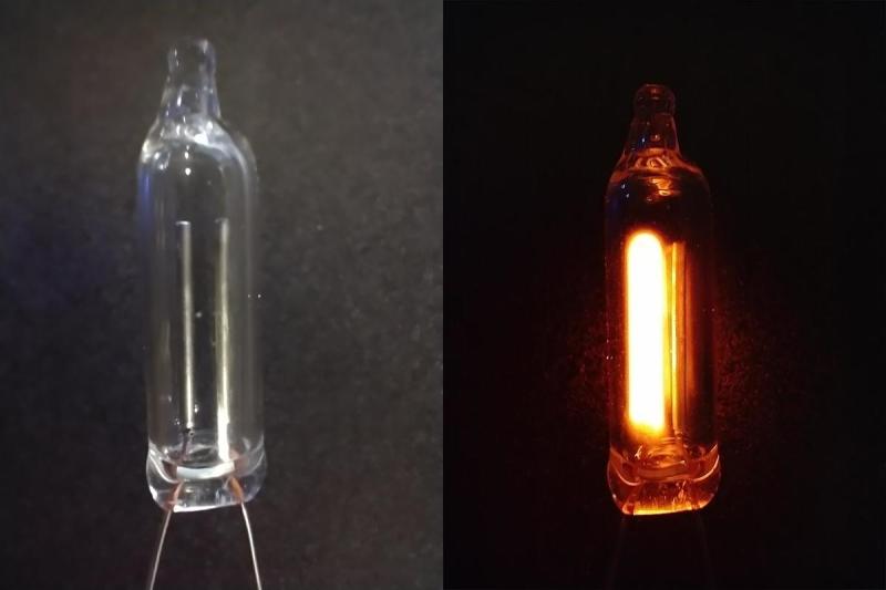
Ah, the humble neon lamp. The familiar warm orange glow has graced the decks of many a DIY timepiece, sometimes in a purely indicating duty, and sometimes forming a memory element in place of a more conventional semiconductor device. Capable of many other tricks such as the ability to protect RF circuits from HV transients, its negative resistance operating region after it illuminates gives us usable hysteresis which can used to form a switching element and the way the pair of electrodes are arranged give it the ability to indicate whether a voltage source is AC or DC. Now, due to some recent research by [Johan Carlsson] and the team at Princeton University, the humble NE-2 tube has a new trick up its sleeve: acoustic transduction.
The idea is not new at all, with some previous attempts at using electric discharge in a gas to detect audio, going back to the early part of last century, but those attempts either used atmospheric pressure air or other non-sealed devices that exhibited quite a lot of electrical noise as well as producing noxious gases. Not ideal.
The new work concentrates on the idea of detecting the ultrasonic emissions due to initial stress relief during metal fatigue failure of large structures such as bridges and oil drilling platforms. Traditionally the only way to do this is with a piezoelectric acoustic sensor, but those are short-lived in harsh environments, annoyingly resonant in frequency response, not to mention, expensive.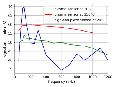
Enter the humble NE2 with its almost flat frequency response in the 200 kHz to 1 MHz region of interest, its ability to withstand operating temperatures of up to 400 degrees Celsius and being a sealed glass container, quite impervious to conditions if you can protect the connecting leads. The operating principle is simple enough, once the neon is ionised and the device is operating in the breakdown condition, pressure variations in the surrounding air are conducted through the glass, which causes pressure variations in the neon next to the electrodes. Take the current signal through the lamp and high-pass filter it, and you’ve got yourself a really cheap transducer. What a device!
To further bestow the virtues of this indicator device of a bygone age, we have a neon lamp based Nixie clock, an NE-2 not-LED matrix display unit, and finally using an array of them to visualise an electric field.


They can also detect electromagnetic waves including light and terahertz radiation. They are technically simple but multi-application devices that were primarily used as indicator lights.
Simplicity is the height of sophistication and any significantly advanced technology is indistinguishable from magic.
They had a lot of uses as circuit elements too.
Years ago I saw a circuit with 5-10 NE-2 in series. One end attached to a grounding rod the other to an antenna. Supposedly they all would flash with nearby lightning. I’ve searched but cannot find the circuit . No idea if this would work?
I entertained the kids by sinking 4 different colored fluorescent light tubes 1 ft into the ground in the 4 corners of our back yard shot an antenna wire into the trees attached to the upper end connector pins and watched the light show from a nearby storm. ………..Bob Best Brooklyn Ct,
This is a very interesting and creative use for neon lamps.
It’s not specified in the linked blog post, but I strongly suspect that the high frequencies measured are not possible in air. I believe air transmission cuts off at around 50KHz, and he’s talking about measuring sound transmitted in a solid (or liquid) medium.
I also suspect that the lamp will be direction sensitive, as sound in the plane defined by the electrodes would cause the electrodes to change distance, while perpendicular sound would cause the electrodes to move in sync. This might be a good thing, as you can then use multiple lamps and correlation math to determine the direction of the sound source in 3 dimensions.
There’s not much information on the blog post, but it’s still a very interesting development. This makes me wonder if seismic detection at the high frequency range would uncover any interesting signals.
Your questions are all excellent! An atmospheric discharge could detect high frequencies, as long as the electrode dimensions resolve half the wavelength. But as you state, air is quite viscous at frequencies above 100 kHz or so. Some bats vocalize as high as 200 kHz, but I reckon you’d have to get pretty close to detect that.
Gas-discharge tubes could be used as microphones (to detect sound propagating in air), but they have poor acoustic-impedance matching (most of the acoustic energy is reflected by the glass envelope). That’s why elastic waves in solids and fluids are a more suitable target for this tech.
I also thought the gas-discharge tube transducers would be quite directional, but initial testing says otherwise! My current hypothesis is that there’s a lot of diffraction inside the tube. A directional tube would be useful, as it could differentiate between shear and compression waves.
Yes, the blog post is terse. I’m working on a peer-reviewed publication that will have all the details.
Please forward me a copy when you’re ready to publish. You can contact me from .IO using the link in my name on this or the original post.
I’d also be willing to be a proof-reader, if you need any.
I’ll be happy to keep you in the loop! I also plan to use .io to post some stuff. I’ll get back to you.
Would like to hear your latest!
Looking forward to the hack that uses this as a covert microphone.
Eyeballing the frequency response, you’d be snooping on bats or (actual) dog whistles.
The roll off in sensitivity at low frequency is due to a high-pass filter, not the transducer itself. For the application I had funding for (detecting metal fatigue in nuclear facilities), the frequency range of interest is 60 kHz to 1 MHz, so we had a high-pass filter at 50 kHz and a low-pass one at 1 MHz.
The video I linked to in another reply demonstrates transduction at audible frequencies.
Some early feedback I got on this tech was the person I was talking to uncomfortably looking up at the fluorescent lights above him and asking: “so you’re telling me they’re always listening to me”?
Fortunately gas-discharge tubes have pretty poor sensitivity for sound waves in air, due to the acoustic-impedance mismatch. Fluorescent tubes would make particularly bad covert mics, because they tend to have switched -mode power supplies operating just above audible. So possible in principle, but it would be hard to extract a signal from the noise in practice.
That,
and that they are so busy making their own noise to probably “hear” very well…
B^)
Do the metal reflectors couple to air better? Or at least, present a much larger area to couple to. As Ren’s comment notes, we certainly can get lots of coupling going from fixture to air. Don’t know what the bandpass characteristics of the actual bulb mounts would be.
As for directionality, would stand-offs on the ends of the bulbs work? With those effectively being the only conduction points you might get sort of a reverse-dipole.
I once found that a neon indicator lamp on a power strip was behaving as a light detector. When the room lights were on, the neon indicator was solid lit, but when the room was dark, it was a slow random flash. I believe peak ac voltage and the neon’s breakdown voltage were close. The photons from the room light lowered the breakdown voltage enough for constant illumination.
I’ve noticed a similar thing. I had an old power strip with a neon lamp in the switch that wouldn’t stay on continuously. If I pointed a red laser pointer at it, it would stay lit until I turned of the laser pointer. It would then return to flickering ramdomly.
Same thing happened to me although I just shined a small, high intensity flashlight at it for the same results. I bothered to try that since I’d read about why this happens somewhere online.
Lowery, Conn, and others used them like diodes to conduct the organ tones to output with sustain-decay and Kinsman divided pitch from 12 master tones down thru all the octaves with neons in their organs, flip flops basically. They would sometimes act up when in the shop with the lid open and bright light overhead. This makes me wonder if the unique sound of the Kinsman was a reaction of the speaker and the neon dividers, more likely they were sort of sawtooth instead of square wave.
There has also been some research in using neon tubes as the “structural” portions of antennas, where the plasma functions as the conductive portion of the antenna and the RF signal is injected as per normal. Can’t remember the name of the paper, and the Google-Fu needed is an exercise left for the curious.
Would be interesting to see some more details on the recommended operating conditions (operating voltage, series resistor) for using this thing as a microphone.
You want high current for the strongest signal. I’ve been told to avoid public disclosure until fairly recently (for patent reasons), but plan to gradually get more info published. Also, for a microphone (sensing sound waves in air) you probably want to use an atmospheric discharge for acoustic-impedance matching. A pickup (sensing vibrations in a solid, like the soundboard of a piano or the bridge of a violin) is easier. I demo that in the video I linked to in another reply. I do plan to revisit the plasma mics from the 1920s now that I had some success on the easier plasma pickup problem.
Somewhere between 1969 and 1971, I read of the reverse transduction, a high voltage audio signal fed to a pair of electrodes in a gas flame, which served as a loudspeaker. It was a brief item in New Scientist. OK, a flame is not an electrical discharge, but both are plasma. The item also mentioned the alternative of a loudspeaker in an enclosure in the gas line modulating the gas pressure, in which case the flame provided some power gain, IIRC.
(Hard to rely on wetware memory over that timespan.)
Yes, plasma speakers (including flame speakers) are more common than plasma mics (not to mention the plasma pickup). Duddell’s “singing arc” was introduced in 1900 and plasma speakers are still commercially available. I think it’s fair to characterize them as a novelty, rather than a viable speaker technology.
I operated a plasma speaker in reverse, that is as a plasma mic, a couple of years ago. I was barely able to get a signal out of the very noisy background. That’s when I decided to focus on gas-discharge tubes instead of atmospheric discharges. However, since then I learned from a friend about “das Kathodophon”, a thermionic-cathode plasma mic, invented in Berlin in 1919 by Hans Vogt, Josef Engl and Joseph Massolle. It’s basically a Nernst lamp used as a mic, and in fact a working replica was made from a modified Nernst lamp in 1928. The thermionic cathode reduces the operating voltage from several kV to less than 500 V, it increases the discharge current by a factor of ten (and therefore signal strength by 20dB), and it makes the discharge more quiescent. The Kathodophon was sold commercially and was in use until the late 1930s. With my fellow Kathodophon aficionados I have formed the hypothesis that non-technical reasons drove it into obscurity. To test the hypothesis we plan to build a replica. The effort is unfunded but benefits from my plasma pickup work.
It would be very interesting to hear about developments – a youtube clip perhaps, so we can enjoy your endeavor. (I will though take the plasma speaker off my bucket list, given your findings. The list is in any event more than long enough.)
The kind interest from Hackaday readers has certainly encouraged me to get more info disseminated! I will gradually work through my pile of project progress reports to DOE, rejected grant proposals and information provided to patent offices to extract what’s fit to publish.
On the separate but related topic of the 1920s plasma microphones, my wonderful collaborators and I have made good progress on understanding the technology based on available documentation, but want to build replicas to learn more. So the timescale for getting information out is probably a year or two. Maybe I can post some sporadic build logs on .io?
In other words it’s possible to use one as a microphone.
Only if you want to record audio above 200kHz.
Like a lot of people of my generation I tried fooling around with neon logic back when vacuum tubes were dying off so power was easy, and you might have only made $3/hr but surplus neons were like a penny a piece so it was cheap fun. TTL logic gates were like $5/dip so …
The biggest problem was rando variations and drift in strike and sustain voltages.
Now I wonder if the acoustic effect in the article might have had some effect on the uncontrollable variations in strike and sustain voltages.
From memory it was something like neons strike around 80 volts or higher and sustain conduction if lit down to 40 volts. So you could have an insane amount of fun building neon flip flops and logic gates with a roughly 60 volt supply and pulses around 40 volts plus and minus and maybe some “penny each” surplus rectifier diodes. The problem is that’s an average set of voltages and they vary individually by more than 40 volts sometimes. Plenty of neons won’t strike on AC line power and peak line voltage is about 170 volts so you can see how my 60 volt power supply and 40 volt control pulses had little effect on worn used up neons… And nothing wears out neons as fast as overdriving them and generally messing around like I was doing.
So maybe my binary counter for a very optimistic binary wall clock was unreliable because of squeeky bearings in the oscilloscope fan (back in ye olden days, Real Oscilloscopes needed cooling fans because they had more than 40 vacuum tubes, but I digress).
Wow, interesting. Could it be used as a microphone for a Venus lander?
I went to my local electronics shop not long back to buy a neon for mains indication on a project I was building, and they sold me the newfangled equivalent of a LED in a metal panel-mount bezel with a couple long leads. I asked for a real neon but they said they don’t sell them anymore.
Do you want a war with Venus?
Recording Venusian conversations without their permission, is a good way to start one.
But maybe we could send them a Google device, and they’ll fall for it just like we did…
A gas-discharge tube could handle the temperature on Venus, yes. See my other comments on acoustic-impedance matching for microphone use, however.
Does anyone know what type of mic they used on Mars recently? The atmospheric pressure on Mars is about the same as inside a gas-discharge tube (1% of Earth atmospheric pressure). Atmospheric gas discharges might make better transducers on Mars than on Earth.
I’m the inventor, big thanks to Hackaday for posting! I see several questions about use at audible frequencies. I did upload a video on that topic: https://youtu.be/y3qPCbSHte8
(there’s some lo-fi plasma-transduced piano music at the end).
TL;DR: neon glow lamps (NE-2 and similar) are microphonic at audible frequencies. Their electrodes tuning-fork (yup, that’s a verb now) at about 1.4 kHz. For use as a plasma pickup, you need a less microphonic tube.
Seems they rediscovered the phenomenon of microphoney that is common to vacuum tubes or valves as they are properly known in British English.
Nope, microphonics is the mechanical resonance between an external vibration and the eigenmodes of structures inside the tube. This is non-resonant, resistive transduction. I discuss this very topic in the video I linked to in another reply. A flat frequency response over almost 1 MHz should pretty conclusively rule out a resonant transduction mechanism!
“eigenmodes”
A new word for me to learn…
https://www.quora.com/What-is-an-eigenmode
I wonder if the process is reversible. Do neons sing if you get the frequency right and apply enough power.
No, they’ll “sing” if you interrogate them severely enough.
B^)
One of the patents I had to comment on in my dealings with patent offices is for a vibration sensor based on a special kind of gas-discharge tube with one flexible electrode close to the inside of the glass tube. It’s US patent 3,718,970, “Electromechanical transducer process” by R. Stanish of Vibrionics Research Co. (https://patents.google.com/patent/US3718970A/en). I think it relies on the variation in capacitance, but the patent doesn’t explain how the device works, just how to make one. Supposedly it works like a vibration sensor with a very narrow bandwidth (4 Hz).
So if you can find a Vibrionics vibration sensor from the 1970s, it might be easier to make that sing than a conventional neon glow lamp with more rigid electrodes.
Perhaps they might be able to modulate a laser passing through the plasma though.
Would this work out as a decent underwater microphone? I understand it will perform pretty bad as an acoustic microphone in air due to the impedance mismatch between the air and the glass. However, with water this would probably be a lot better (although there is still one impedance mismatch from the glass to the plasma). I could definitely imagine some cool applications for that, maybe a DIY sonar system or a dolphin detector (they use ultrasound for echolocation and communication).
Yes! I have tested it in water, with a 87 kHz “pulser” (ultrasound transmitter). It worked great! In fact I measured the highest signal strength so far in this case: 150 mV peak-to-peak (without amplification). Ultrasound propagates really well under water, so the excellent high-frequency performance of the plasma transducer is very useful for this application. I did submit a proposal for wideband ultrasonic underwater communication last year, but it was declined.
Dolphin listening device. Although the em field might attract a few sharks.
I recall a little 1960’s kids “science” toy that was about 3″ long and consisted of two ~1/2″ metal spheres separated by a short length of plastic tube. (I guess to make it look a bit like a miniature Van De Graff generator) An NE-2 type bulb stuck out through one of the spheres. The goal was to get yourself set up with a static electric charge (e.g. rubbing your hair with a balloon, etc.) while holding the thing by the plain end and then touching the neon end to discharge (to a door knob, or perhaps your sister) and get a little flash of light.