While the ESP32 is clearly a superior piece of hardware, we think you’ll agree that the ESP8266 is just too useful not to have a dozen or so kicking around the parts bin at any given time. Cheap, easy to use, and just enough capabilities to bring your projects into the wonderful world of IoT. But if you really want to get the most out of it, you’ll eventually have to skip the development board and start working with the bare module itself.
It can be a scary transition, but luckily, [Ray] has collected some notes that should prove helpful for anyone looking use modules like the ESP-12F in their own custom PCBs. From different tips on making sure the power-hungry modules get enough juice, to cost cutting measures that help reduce the ancillary parts needed in your circuit design, it’s a worthwhile read for new and experienced ESP8266 wranglers alike.

For example, [Ray] talks a bit about using the infamous GPIO10 pin. This pin is on the rear of the ESP8266 module, and on many development boards, it isn’t even connected. That’s because its internally hooked up to the ESP8266’s SPI flash chip, and using it can cause problems if you’re not careful. But as explained in the blog post, as long as you make sure the flash mode is set to “dual IO” (DIO), then GPIO10 can be used just like any other free pin.
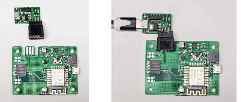
We also really liked the tip [Ray] shares at the end for making your boards more easily programmable. Sure you can leave an unpopulated header on the board, or fiddle with some pogo pin setup, but his edge connector approach is quite clever. Just slip the programmer on for the initial burn, and then after that you can update over the air.
There’s no denying how easy it is to throw something together with an ESP8266 development board, but we’ve covered so many incredible projects that have made use of the bare module’s diminutive dimensions that you’ll ultimately be missing out if you don’t cut out the middle-man.


Liberating the ESP8266 from its proprietary wifi stack?
great, where is your open source project?
There: https://github.com/espressif/ESP8266_RTOS_SDK/issues/1 7 years old, since no source code.
You can find easily socket board for programming/developing with bare modules on ESP32. I assume the same exist for ESP8266.
Yep! https://www.ebay.com/itm/323204866794
That kind of programmer is the right tool to program the device before soldering it, but once you got it soldered, you obviously can’t use it anymore. Also it is useless if you do let your favorite PCB manufacturer make the assembly for you.
In Circuit Programming is still my favorite, and you only need 4 pins (3.3V, TX, RX and GND), which is still a very small footprint! You can add the BOOT pin if you don’t want to put a switch on your final product PDB.
Ota?
OTA only works for the second or greater programming. Your initial programming of an ESP has to be via wire. If you’re having it manufactured then you either have the manufacturer program them or you devise a method of doing it yourself.
In either case plugging one in, waiting for it to boot, connecting, updating, validating, shutting down costs a lot of time/money. Pin programming is much faster and more repeatable.
I’ve made one that can still be used after soldering the module!
https://hackaday.io/project/163220-esp8266-12e-pogo-programmer
The ESP8266 is nearing the end of its life. I would base new designs on the ESP32-C3 which is the same price.
https://www.espressif.com/en/products/socs/esp32-c3
ESP32-C3 module is smaller too — 10.6 x 13.2mm
Maybe, but none in stock at Digikey.
In my Luddite world, I never HAD a development board for the ESP8266. I bought 0.1” footprint adapters and then made my own. Either I’ll use small 3.3v RS-232 converter modules or a USB to 3.3v serial adapter cable if the project won’t ordinarily use serial communication. I feel that in the long run this is less expensive.
“The wonderful world of IoT” who the heck are you kidding ? IoT is a rubbish concept.