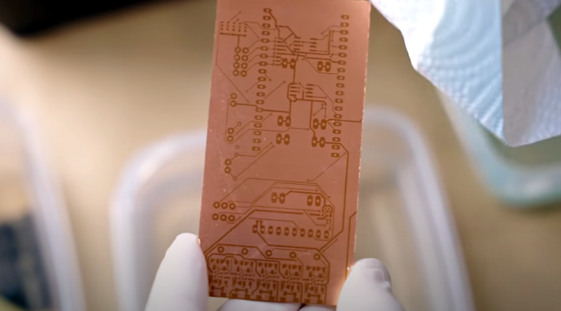
We always enjoy [Thomas Sanladerer’s] 3D printing videos. But his latest isn’t only about 3D printing. He shows how he uses a DLP printer — which has UV light, after all — to expose PC board blanks with great results. Honestly, once we heard the idea, we immediately saw how that could work it is surprising more people aren’t taking advantage of their DLP printers like that. Of course, [Thomas] does his usual thorough treatment of the topic.
Really, this isn’t exactly 3D printing even though it uses a 3D printer. Exposing boards with UV light and artwork is an old process that has been around for years, usually using transparency film and a UV light source. With a printer, you can create artwork digitally and the UV light source is already there.
We liked his test strip method for dialing in the exposure time. Reminded us of our old darkroom days. He also tried using resin as a resist on a bare copper board but that didn’t seem to work as well as you would hope.
The first method, though, makes it painless to get the artwork on the PC board — even easier than laser toner transfer or direct laser exposing it. However, you still have to do the chemical steps and our least favorite part, drilling the holes. Maybe a good argument to stick with surface mount.
We love and respect the desire to do things for yourself and if you own a 3D printer, you probably do too. But unless you are in a big hurry, PCBs are cheap to have professionally done now (as we once predicted) and it really doesn’t make sense to create them at home, especially since it is hard to replicate plated holes, solder mask, and it is extra work to silkscreen the boards, too.
Still, if you need a quick-turn prototype or you just want the satisfaction of making your own PCB, don’t forget that your DLP printer is a ready-made UV exposure system.


This is an LCD 3D printer, no DLP inside!
Pretty slick idea
I wonder how it would go if you used a 3D printer (perhaps with a finer nozzle) to print plastic as a mask and then etch?
I the video he mentions that you shouldn’t saw PCBs (nasty dust). The nasty dust is from the fiberglass and causes a medical condition (silicosis) which causes permanent damage to the lungs and a reduced capacity to breath. He didn’t mention that you can have the same problem from drilling PCB material.
I used to make prototype boards as single sided with no holes (Zero). I used small capacity CPLDs to rout signals so I didn’t have the routing problems normally associated with single sided boards.
It might seem an odd way to do things but there are advantages. 1) I have a gazillion XC9536XL’s in the junk box. 2) PCB trace error – no problem – reroute in the CPLD 3) Oops need some more glue logic – no problem do it in the CPLD 4) Protocol error – CPLD again 5) Want to make something using the same main components – reprogram and re-use and old board. Tips: Use lots of CPLDs, chain the programming lines. Route 50% of IO pins to other CPLDs for better re-use. Use ZIF sockets. Make everything surface mount: bend DIP pins out or better still DIP (ZIF) sockets. Lots of Headers ie 8 pin SMT header can be used with an adapter for a VGA connector or a couple of SPI / I2C whatevers.
How about an article on how you do this Röb. Bill
+1
I’ve shifted house and don’t have the room or equipment for this old hobby stuff like making PCB’s. I’m mostly doing bucket list stuff now. I just escaped lung cancer earlier this year and it looks like round two (waiting for results) this time in the bowels / colon and spine – not good at all.
I did however find some pictures of an old project with just one CPLD that shows the concept so I try to get that up on hackaday.io in the next day or so and I’ll come back and post a link. As a spoiler, it’s an 8 bit IDE HDD (and compact flash) interface for a retro computer: Amstrad CPC 6128 otherwise known as a Sinclair Spectrum +3 I think.
Can confirm silicosis as 28yr veteran working on classic cars. Best way to deal with fiberglass dust is a dust mask with rubber face seal (those garbage white paper ones from the hardware store let the dust right by cuz they don’t seal).
See those headlights in your mirror coming up fast? That’s ARM.
Best way is to wet it down and drain it off so that it doesn’t get into the air in the first place.
I think direct pcb print with laser printer is the best hack I ever did for myself. Works great since years. For sure faster than any other known (by me) low cost method. resolution great , two sided pcbs easy with marginal alignment error. I recommend to anyone capable to dremel to invest some time and money to this type. there are online some good plans, I did for myself “pantum pcb pronter” , but it was years ago, so probably today better choices are available (not to mention that probably my printer is already out of stock…
I actually succeeded to make PCBs with SLA 3D printer and its UV resin. It is important to clean perfectly and give some roughness to the copper surface of PCB.
Although it is in Japanese, the method and results are written at
https://shiura.com/dfab/pcb/
Smart use of a resin printer! Note that Elegoo mars2 is a LCD /MSLA printer, not DLP…
What needs to be figured out is layer alignment.