Electromagnetic fields are everywhere, all around us. Some are generated naturally, but in vast majority of cases, it’s we humans that are generating them with artificial, electronic means. Everything from your mobile phone to the toaster will emit some sort of signal, be it intentional or not. So we think it only befits the general electronics-orientated hacker to have some way of sniffing around for these signals, so here is [Mirko Pavleski] with his take on a very simple pair of instruments to detect both static and dynamic electromagnetic fields.
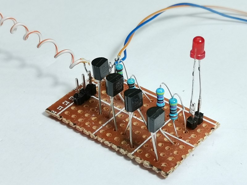
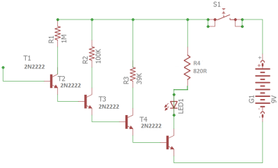
The first unit (a simple electroscope) uses a cascade of 2N2222 NPN bipolar transistors configured to give a high current gain, so any charge near the antenna will result in increasing currents in subsequent stages, finally illuminating the LED. Simple stuff.
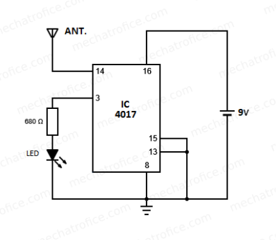
The second unit relies on the extremely high input impedance of the old-school CMOS 4017 decade counter, which is likely of the order of 100 MΩ or even more. Normally you would not leave such a CMOS input floating, or even connect it with too long a PCB trace — lest it pick up a stray signal —but for detecting alternating EM fields, this appears to work just fine. Configured as a simple divide-by-ten, when presenting 50 Hz AC, the LED can be seen to flash at 5 Hz.
Simple stuff, and this scribe has all those exact parts in the junk box, so will be constructing these shortly!
We’ve covered electroscopes for years, here’s a modern twist on a famous classic experiment, and some hair-raising experiments to get you started.


“sorry, but [Mirko] is from North Macedonia, and they use 50 Hz AC”
I wonder why you feel it necessary to appologise for the creator of these devices having 50Hz AC mains? HAD has a large international readership and much of the world uses 50Hz AC.
I feel the same as you about that statement!
https://en.wikipedia.org/wiki/Mains_electricity_by_country
The majority of the world is, regarding frequency. Now for the real salt:
What is the best plug type? I love Schuko!
UK … definitely designed by lego … if you have ever stood on a piece of lego
I’m the same. I read that and thought what the heck is that all about.
We also use 50 Hz here in Oz, so jumping in ahead of the rest with an apology for …er, whatever it was that needed apologising for :) I reckon it’s just a very unfortunate poor choice of phrasing on an otherwise interesting article.
The circuits are simple enough that playing with them won’t take much time away from my yak-shaving activities. Would there be a way to make the sensitivity of either design adjustable?
Obviously foreigners read the site, but it’s written primarily by Americans for an American audience.
I’d say that, be ause it’s the way I view it. Butthen itdoesn’t explain Jenny list.
I have a power transformer rated for 25 cycles. I’ve had it for fifty years, it didn’t seem too old then. I gather Niagra Falls generated that for some time.
I think you owe an apology to [Jenny List] for what you just called her!
B^)
So, which are foreigners? Them or us?
I am reminded of an exchange that occurred in an episode of The Goon Show …
“Gentlemen, Intelligence have determined that the people attacking us are the enemy.”
“Good heavens! Do the enemy realize this?”
“Oh, no, sir. We’ve got ’em fooled … they think WE’RE the enemy!”
Since less that 5% of people live in the United States, why would HackADay be read primarily by Americans? The numbers just don’t add up.
~4.2% of the worlds population is in the USA
4.8 percent of the world speak English natively, about 13% of the worlds population can speak English.
If HackADay was not primarily targeting the US, then they should probably have the site in Spanish since 4.9 percent of the world speak Spanish natively. Maybe a sister site called HackearDía.
So, HAD targets English readers, the majority of which (by your own computation) live outside the USA; simple comme bonjour.
It would be “HakearUnDia” :-)
We want site analytics!
According to this analysis (link below), 37.66% of visitors to HaD are from the United States, which means the “foreigners” are actually the natives, and the natives are the foreigners, with regard to site visitors.
https://www.similarweb.com/website/hackaday.com/#:~:text=Traffic%20to%20hackaday.com%20by%20country
To use HaD lingo for a quick browse, you need to do a Deep Dive into the data. I think we can safely add Canada which gives a new total of 44%. Ignoring the 50Hz tragedy we can add the UK and now it is over 50%. Add the rest of the English speaking lands and it is pretty solidly Englishy.
I wouldn’t mind seeing the rest but you have to join something.
You sound like you should go into politics or comedy, either would be a good fit :p
Sorry for the confusion about my use of the words “native” and “foreigners”. I meant it in the national sense, not the language sense!
Since HackADay *is* an English language site, presumably only English readers in general visit HaD. So language isn’t a factor here. Since more than 64% of site visitors are not from the United States, I meant that in the sense of site visitors, from the US are the “foreigners”, being in the minority, and the rest of the world were the “natives”.
Just think, in Japan you could use this device to tell where you are!
At least which side of the island you are on. But you could just look at the power outlets and tell.
Could something like this be used as an RF harvesting circuit? I’m thinking about powering some BLE chip that goes to sleep for long periods of time.
This circuit(s) require power supply – they amplify a very week signal to the order of magnitude that can drive LED, so you “get” micro wats for free, and add mili wats from battery to get that LED blinking :)
For RF harvesting you need “something” that does not require an external power source
Both this and an inductive charger use antennae to do things with EM fields. The differences are:
-charging inductively relies on tuning an LC circuit/antenna around to the frequency of the exciting radiation and gathering energy from the inductor in that current.
-These noise detectors rely on an external power source (battery) to boost oscillations induced in the antenna by exciting radiation. You don’t have to
Basically, these EMF detectors use energy to actively detect EM activity, whereas wireless charging uses careful consideration on both the emitter and receiver side to transfer a reasonable portion of the power going into the charging circuit.
I suppose it’s theoretically possible to harvest energy from incidental EM fields, but you’d have to be smart about it. Maybe tuning an oscillator/antenna to your local mains frequency, and then placing your widget in a place where it’d be likely to pick up mains radiation. Or you could do the same with 2.4GHz, which is everywhere.
Now that’s jogging my memory bank. After 10min of searching, I found the following, which uses 2.4GHz radiation to light an LED. Obviously there’s some power to be had. Distance will be critical, as the available energy decreases as a square of the distance from the source, and neither mains lines nor 2.4GHz transmitters are typically designed as inductive charging antennae:
https://hackaday.com/2021/10/16/the-simplest-way-to-spot-2-4ghz-rf/
That thing is probably averaging 5-10mA at just under 2V when *very* close to the 2.4GHz emitters. That’s more or less enough to power an MCU, though it doesn’t have any rectifying losses, as the load (LED) is part of the rectifier. If you wanted to make a BLE widget similarly, you’d probably want to find a good energy harvesting PMIC with a boost charger for a li-ion, then run your NRF, ESP32 or what have you (I think ESPs are known for being relatively power greedy, I think there are some power sipping STM32 options among others) off of battery voltage. Probably have it on a wake interrupt based on a voltage comparator input to make sure you have enough charge for transmission. First, though, you’d really want to just design a simple RLC circuit/antenna to test if you can even make the power budget such a setup would require and wave it around in areas you’re hoping to drop the widget.
I think you could use a pair of darlingtons instead of 4 cascaded 2N2222. The MPSA13 has a gain of 10k and 2 of those would be the same as 4 2N2222 transistors. It could perhaps be more sensitive than the 2N2222 due to the pairs being coupled on the same dies.
But you may not have a darlington around, while many have endless piles 2N2222s around, handy and virtually free
I imagine it should be “whatever arrangement of devices will net you ‘x’ hFE or thereabouts”. If you happen to have a bin of Darlingtons, or want to set up Sziklai pairs, go for it. I still have nearly _3,000_ (minus probably 100) 2N2222 TO92 devices I picked up for cheap years ago, but these days I use SMD for virtually everything, so the TH parts kind of just sit there. Even for normal hobbyists, their kit should have a few standard NPNs such as 2N2222, whereas packaged Darlington devices are a wee bit less common.
For me, an opportunity to use four of those old TH devices would be most welcome, though honestly, I’d just as soon etch the PCB and use SMD if the project is worth building (less drilling). I have some old CD4017, so I just might make this in the coming weekend if I have some time.
My 2N2222 stock averages around 150 hFE, so a 2-stage Darlington made of them should roll in at about 22.8K. The full-on 4 stage maths out at almost 520 million hFE.
Darlingtons are wired as common emitter, this circuit is common collector.
Darlintons are wired as collector followers, this circuit is emitter followers.
Depending on where you are and when you were taught.
Does it have to be current multiplying? A 75HC04 can be used as 6 amplifiers.
And is ti fair to call this an electrometer, which is an invention in which gold leaves are repelled from each other when they are charged, and in a measurable way?
The current multiplying is only part of it.
The input impedance needs to be exceptionally high otherwise you’re essentially shorting out what it is that your trying to amplify.
The 74HC04 shows an input current of 1uA so it has a fairly high input impedance and may be worth a try.
Even simpler and better, a single FET, courtesy of the inimitable Alan Yates: http://www.vk2zay.net/article/9 (from 20 years ago).
That’s really neat, along with http://amasci.com/emotor/chargdet.html . Has anyone made a more full featured digital version with Arduino?
If you fed this into an op amp to constrain the output to 0-5V into an arduino’s adc that would probably suffice.
I built something vaguely similar as a retrofit tool for a monoprice mini 3d printer repurposed to do the pretty boring job of mapping EMI off a circuit board. By far the hardest part was getting the dumb printer to reliably talk to the host computer the way octoprint does.
Just run it from 5v instead of 9v
Smellsofbikes, so you have any more info about your EMI scanner? I’ve been thinking of doing something similar and would love to see an example! I was even planning to use the same 3D printer as the base of the build.
One big issue with your source is that the JFETs are reverse biased (look it up online). The source terminal of an N-channel JFET should be positive relative to the drain. The gate input should be positive relative to the drain to “turn it on”. The LED is biased correctly as shown in the basic diagram (cathode to negative), assuming that the JFET is ON. The location of the earth ground makes no sense, unless there is some other reason to have it that way (and there doesn’t seem to be any, since he states that “ground” is optional). Common issues with unvetted sources on the internet.
The symbol for the N-JFET indicates a symmetric JFET – source and drain are interchangeable.
Build one and try it. It works quite well. I’ve built bunches of them, and never had a problem
Also it’s a depletion mode JFET (Junction Field Effect Transistor).
What people generally refer to today as a “FET” is an Enhancement mode IGFET (Insulated Gate Field Effect Transistor)
I used to have a cheapo battery powered vellman scope, it had a BNC connector – I stuck the areal from my scanner in it, and could see the mains power at 50hz, and for example a power spike from across the room when a crt was switched on.
Antenna/ aerial, sorry typo.
I suspect this will work the same way if all the collectors are tied together. You just need one collector resistor for a LED.
No, The collector resistors are the input impedance of each stage.
When I learned how NPN and PNP transistors worked, I cascaded them together like this https://i.imgur.com/CVeidFC.png and with enough stages I could light the LED by waving my hands from several feet away
I think you may the emitters and collector reversed ?
a very timely article.
>50 Hz AC (sorry, but [Mirko] is from North Macedonia, and they use 50 Hz AC)
Why sorry? Such an US-American centered comment.
Tried this circuit and id not worked. Asked for help at https://electronics.stackexchange.com/questions/605238/why-the-led-stays-on-all-the-time-in-this-very-simple-circuit/605243 they concluded that the circuit is not ok. I wish it worked :(
I made the first circuit (with the transistors). It’s really cool, but doesn’t behave for me like an electroscope. The LED lights whenever I move the probe near any solid object (meal, a kitchen towel, wood, leather, etc.). If I rapidly slide a ziplock plastic bag under the probe, the LED lights. If I move the probe around in the air nothing happens. If I blow on it nothing happens. But whenever a solid object moves toward it or away from it (especially something plastic or something like a pillow that’s filled with polyurethane foam), the LED lights up. If I hold any of the objects still the LED goes out, then if I wiggle the object around the LED comes back on. Anybody know what might be causing this? Thanks!
It’s electrostatic current.