Most crystal radio receivers have a decidedly “field expedient” look to them. Fashioned as they often are from a few turns of wire around an oatmeal container and a safety pin scratching the surface of a razor blade, the whole assembly often does a great impersonation of a pile of trash whose appearance gives little hope of actually working. And yet work they do, usually, pulling radio signals out of thin air as if by magic.
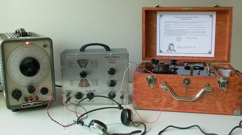
Not all crystal sets take this slapdash approach, of course, and some, like this homebrew multiband crystal receiver, aim for a feature set and fit and finish that goes way beyond the norm. The “Husky” crystal set, as it’s called by its creator [alvenh], looks like it fell through a time warp right from the 1920s. The electronics are based on the Australian “Mystery Set” circuit, with modifications to make the receiver tunable over multiple bands. Rather than the traditional galena crystal and cat’s whisker detector, a pair of1N34A germanium diodes are used as rectifiers — one for demodulating the audio signal, and the other to drive a microammeter to indicate signal strength. A cat’s whisker is included for looks, though, mounted to the black acrylic front panel along with nice chunky knobs and homebrew rotary switches for band selection and antenna.
As nice as the details on the electronics are, it’s the case that really sells this build. Using quarter-sawn oak salvaged from old floorboards. The joinery is beautiful and the hardware is period correct; we especially appreciate the work that went into transforming a common flat washer into a nickel-plated escutcheon for the lock — because every radio needs a lock.
Congratulations to [Alvenh] for pulling off such a wonderful build, and really celebrating the craftsmanship of the early days of radio. Need some crystal radio theory before tackling your build? Check out [Greg Charvat]’s crystal radio deep dive.


Wow, just wow.
Agreed, wow indeed
What? It’s not 3d printed ….
On a more serious note that is a work of art – if you’ve never taken a trip down the crystal set rabbit hole it’s well worth it. Some of the creations are outstanding.
Thanks. This project was in fact inspired by some of the other outstanding creations. As for 3D printing, I’ll be doing a bit of that in a future project. :)
Very nice, not only a working retro radio but a beautiful piece of art too,
Excellent!
I knew I was saving those 1N34s for something.
I very much enjoyed this.
One question though: The OP says: “, I used the 1932 Australian “Mystery” design. Well known for its sensitivity and simplicity, and despite being popular, nobody knows exactly how the “Mystery Set” works to this day ”
Can some one explain why this circuit is supposed to be “mysterious?” I see there is no DC ground on the primary side, but I’d guess there is sufficient capacitive coupling between windings to give the RF a return path to ground.
If you replicate this project: The end of his coil form (container) appears to be tin. If so, I’d have removed that and replaced it with a glued-in wood spar. A disk of metal in proximity to the coil will act as a shorted turn, reducing the receiver’s selectivity and likely, its sensitivity, too.
Also, don’t use cardboard coil forms unless you varnish or polyurethane them to seal them. I have wound beautiful and neat coils, only to return to them months later and find them a loose jumble. Cardboard tubes can change dimensions significantly as ambient humidity changes.
I love the style of switch used in this radio. I would have used brass instead of steel, however. The switch contacts can be made from brass screws. If you chuck the screws in a drill, and dress them with a file as they turn, you can remove the screwdriver slot and create a nice create a nice contact.
If you file down a brass Philips…. is that cross-dressing? :-D
Spider web coils and basket coils are neat, too.
In contrast to traditional air coils, they have a high Q. And they look more civilized, hi! :D
The flat versions can be build from a CD case or a beer coaster, for example.
Instructions here:
https://pe2bz.philpem.me.uk/Comm/-%20Receivers/-%20Crystal/Prj-010-/spider.htm
It really works, tried it out myself and counter checked with a digital capacity/inductivity meter.
Two other cool sites are
Jogi’s Röhrenbude (Jogi’s Tube Shack)
https://www.jogis-roehrenbude.de/
And Wumpus (world of old radios)
https://www.welt-der-alten-radios.de/detektor-bauprojekte–80.html
They’re in German, but online translators can help.
Vy73/55s,
Joshua
I have an old wooden spool with 2 pounds of #32 (.008″ or 0.2mm) copper with cotton wound insulation. I knew I was saving it for something! It has two layers of fine cotton winding and is still only .0015″ or 0.37mm.)
For the contacts, you could also just fill the slots in the screws with solder, sand it smooth, and plate with nickel or gold to make the solder invisible and improve conductivity.
Very cool! My father still has a small collection of German germanium diodes. OA91 etc?
Nevertheless, please let’s never underestimate a real detector from the 19th century. Glas diodes are fine, but not superior necessarily. A well tuned crystal detector can provide a smooth AM demodulation, better than a glas diode.
The razor blade and safety pin can make a pretty good diode, but it takes patience. Natural galena ore and a safety pin point contact works too. You can also melt down some bar type solder and throw in a touch of of flour of sulfur to make a galena substitute. The US Boy Scout Handbook from the late 1960s had instructions for making a crystal set with the latter type of home made detector. The scout book also suggested making the capacitor from aluminum foil and waxed paper.
Aren’t some Shottky diodes even lower voltage than the germanium type?
Nominal forward voltage, sure. However, what counts for a crystal radio is forward voltage at very tiny currents (it tends to go down with current, in a non-linear relationship), which you usually won’t find on a data sheet – Ge diodes tend to go lower in such conditions than a Schottky diode.
Some Schottky diodes have very low voltage drops and can be as good as or better than germanium detectors in crystal sets but unless you’re buying pre-tested and selected Schottky diodes, you will need to purchase a package of a few dozen or more to test and hand-pick as performance can range from weak or almost no detection to excellent performance. Look for Schottky “signal diodes” such as BAT46 or BAT48 to replace germanium.
As a workaround, it’s also possible to add a simple battery to the diode. At best, it has the same voltage as the diode needs. A potentiometer can act as a voltage divider here, also.
That adds a nice bias voltage that makes the diode operational with much less received energy from the ether, thus improving reception of weak signals.
Just add battery’s + to anode, – to the whole circuits ground (earthing).
If you make the battery yourself, say, using a piece of lemon (or a glass of lemon juice) and copper+zink wires, then it’s still a self-sufficient unit that needs no commercial battery and works in a post-apocalyptic world.
Or use a copper wire + a carbon piece (fron old pencil etc). That way, everything is home built still.
And the receiver still works without the battery, just less efficient.
This 300b wants to be a guitar amp in no time at all.
nice, meybe ading a DAB+ ?
Nice looking for sure. How well does it work, especially at shortwave?
Some wine can be purchased in hinged wooden presentation cases that are roughly the size of an attache case. I have one set aside for a future radio project, probably a reconstruction of a clandestine tube HF transceiver.
What size fixed cap is on the meter terminals?
I used a DC Minus Zero Plus -10uA – +10uA analog meter. This a bit more sensitive. Some radio stations signals are backwards, so to speak, and the meter in the given article above won’t read them. I used a 1N34A diode and 10uf barrel type cap. Anything above four or below four on the meter is enough power that I can use my headphones and not my small guitar amp. There is one caveat though, when using the meter there will be a reduction in audio power. Best to have a bypass switch.
I have two types of headphone connections. One, 32 ohm with a 6v x 6v transformer for low impedence, and the other is a 10,000 ohm I use for straight up high impedence. (Not at same time) The latter is the best. I have always wondered why there were never any transformers used in WW 1 . Now I know. Lol! They didn’t them. The headphones were typically 2k and up. “Happy Hunting!”