You’ve built a robot crammed full of servos and now you settle down for the fun part, programming your new dancing animatronic bear! The pain in your life is just beginning. Imagine that you decide the dancing bear should raise it’s arm. If you simply set a servo position, the motor will slew into place as fast as it can. What you need is an animation, and preferably with smooth acceleration.
You could work through all the math yourself. After half an hour of fiddling with the numbers, the bear is gracefully raising it’s arm like a one armed zombie. And then you realize that the bear has 34 more servos.
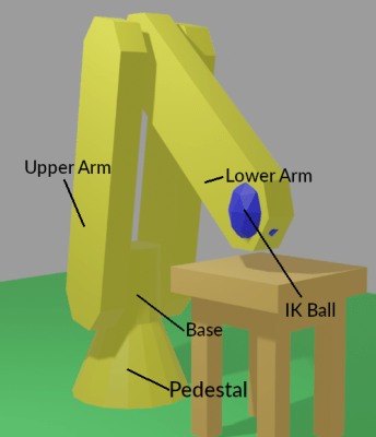
Fortunately for everybody who’s done the above, there’s Blender. It’s all about creating smooth motion for animations and computer graphics. Making robot motion with Blender is, if not easy, at least tolerable. We made a sample project, a 3-axis robot arm to illustrate. It has a non-moving pedestal, rotating base, upper arm, and lower arm. We’ll be animating it first in Blender and then translating the file over to something we can use to drive the servos with a little script.
Now, Blender is notorious for a difficult user interface. The good news is that, with revision 2.9, it moved to a much more normal interface. It still definitely is a large program, with 23 different editors and literally thousands of controls, but we’ll only be using a small subset to make our robot move. We won’t teach you Blender here, because there are thousands of great Blender tutorials online. You want to focus on animation, and the Humane Rigging series is particularly recommended.
Here are the major steps to animating a robot:
- Make a ‘skeleton’ (armature) that matches your robot
- Rig the armature so that it moves like your robot and is convenient to animate
- Animate the armature
- Export the servo positions to your robot control program
Generally, computer animations consist of an armature and then the mesh for the body that hangs on it. For a robot, we don’t need the mesh, just the armature, because we’re not making a movie. Still, the armature does need to match the hardware size. Import CAD files or build atop a photo or just measure the robot.
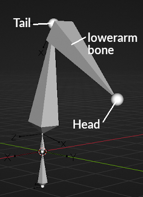
The robot’s rest pose is the reference position of the joints, where the robot is when the axes are at zero. Ours is pointing the arm straight up.
Bones pivot about the tail, and the head is ‘where they are’. Your shinbone’s tail is your knee, and your shinbone’s head is your ankle. Bones can have parents. Your shin bone is a child of your thigh bone. If you move your femur (thigh bone), your shin goes with it.
Bones only rotate on certain axes. Knees only swing back and forward, not side to side. You can twist your wrist, but not your fingernails. They also have motion limits. You probably can’t bend your knees backward.
Hinge joints only rotate, but some bones can scale (a soft robot), or translate (a CNC router).
There are even more complex constraints. The front wheels of a passenger car steer together. The rods on a steam locomotive stay on their pins. The dog can move freely to the limit of it’s leash.
The animator might not want to pose by positioning the bone. Animating a character’s eyes by setting their angles would be awkward. Far better to have an extra target bone that the character always looks at, and constrain the eyes to look at the target. We usually curl our fingers all at once, and we curl all the joints on a finger at once. So how about an extra bone that controls everything at once?
An armature with all these extra control bones and constraints is called a rig. Blender has powerful tools to build rigs like this.
Our example’s first bone, pedestal, represents the robot’s pedestal, the part bolted to the floor. Bones are posable – that’s the point, you can animate them. But this bone never moves, so we locked everything – the location, rotation, and scale.
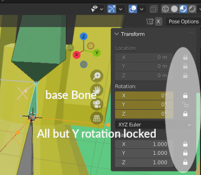
The base rotates on the pedestal, so the base bone is a child of the pedestal bone. base‘s head is at the pivot for the upper arm. The base rotates on the base bone’s Y axis. That’s it’s only motion, so we locked all the other axes.
The other bones are much the same. upperarm is a child of base, with its head at the elbow. lowerarm runs from the elbow to the wrist. These joints are oriented to turn along local Z.
The armature now works. Select (pose mode) the base and turn it (Y rotation) and the arm bones rotate as well. If you mess the position up experimenting, just undo or set the unlocked axes to zero.
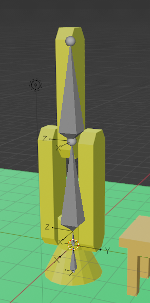
Our sample robot has a simple mesh that moves with the bones so you can see the robot move.
But its still possible to put the robot in positions the hardware can’t do. Lets say our sample hardware robot base can only rotate 90 degrees each side of center. We can keep the animator from making impossible moves with bone constraints. We added a limit rotation constraint to each bone.
Interacting
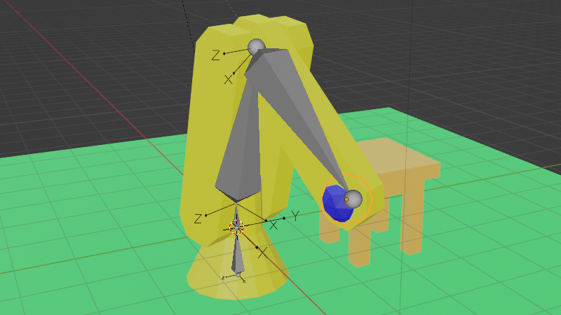
This is great, but now we want our robot bear to grab a present. How will the robot interact with the outside world. The solution is inverse kinematics (IK). IK lets us say where we want the wrist, not where the shoulder and elbow joints are. So we added a ball named IK to the scene and added an IK constraint to the lowerarm to try to reach the ball.
If you’re following along, move the sample timeline to frame 120, so the IK is on and you’re not messing up our animations.
The robot wrist now is ‘grabbing’ the IK ball. In object mode, select the ball and use (g key) to ‘grab’ it. Drag to move the ball around. The robot neatly follows along, and the joints set themselves to do what’s needed. Much more convenient.
If you want to poke around in the IK constraint, its home is lowerarm. In pose mode, select lowerarm and the bone constraints tab in the object properties editor on right. The IK constraint lives here.
A brilliant bit of Blender is that almost anything can be animated. Most values have a small white dot on their right. Clicking that turns it to a diamond and makes the value animated. We did this to “Influence”, which is the ‘strength’ of the constraint.
Animation Time
We’re now ready to animate. 10 FPS is fine for most robots — set this in Render Properties. We just put all the animations one after the other in the timeline, and grab the slice we want, so maybe ‘bear chuckles’ is frame 50 to 70.
Back when we were moving the bear arm by typing in numbers, we had to do every frame. Thankfully not needed now. We only have to pose the robot on enough frames to get the behavior we want. These are keyframes. Blender does the frames in between.
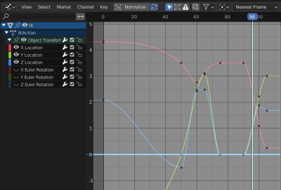
By default Blender adds the ease in and ease out, so the servos accelerate smoothly. You can select the IK ball and check the ‘Graph Editor’ if you want to see the curves.
There’s a difference between posing and making a keyframe. Posing the robot doesn’t change the animation. It’s only making a keyframe (i key) that changes the animation.
In frames 50 to 75 the robot picks something up and moves it. Notice that making the animation was just ‘move ball, make keyframe’ four times. It took under two minutes to make the entire animation. We never animated the actual robot — the inverse kinematics took care of it for us.
From 90 to 105 the robot avoids a nearby table while setting something on it. In practice we would have to run these on the real robot and tweak them a half dozen times. Doing that without software support would be a nightmare.
From Animation to Robot
We’re ready to move our animation to our robot control program. There’s a nifty hack for this. The de facto standard for computer animation files is ‘BioVision Hierarchical’ format (bvh). Blender can export it, though you might need to enable the plugin and select the armature. Here’s a sample.
HIERARCHY
ROOT pedestal
{
        OFFSET 0.000000 0.000000 -1.000000
        CHANNELS 6 Xposition Yposition Zposition Xrotation Yrotation Zrotation
        JOINT base
        {
                OFFSET 0.000000 0.000000 1.000000
                CHANNELS 3 Xrotation Yrotation Zrotation
                JOINT upperarm
                {
                        OFFSET 0.000000 0.000000 0.500000
                        CHANNELS 3 Xrotation Yrotation Zrotation
                        JOINT lowerarm
                        {
                                OFFSET 0.000000 0.000000 3.100000
                                CHANNELS 3 Xrotation Yrotation Zrotation
                                End Site
                                {
                                        OFFSET 0.000000 0.000000 3.100000
                                }
                        }
                }
        }
}
MOTION
Frames: 251
Frame Time: 0.100000
0.000000 0.000000 -1.000000 -0.000000 0.000000 -0.000000 -0.000000 0.000000 -0.000000 -0.000000 0.000000 -0.000000 -0.000000 0.000000 -0.000000
0.000000 0.000000 -1.000000 -0.000000 0.000000 -0.000000 -0.000000 0.000000 -0.000000 -0.000000 0.000000 -0.000000 -0.000000 0.000000 -0.000000
0.000000 0.000000 -1.000000 -0.000000 0.000000 -0.000000 -0.000000 0.000000 -0.000000 -0.000000 0.000000 -0.000000 -0.000000 0.000000 -0.000000
... lots of lines of this ...
While this looks unlovely to parse, there’s a hack. We don’t care about the top part (the skeleton). We just want the frames of motion data from the bottom.
Find the line number of the line after ‘Frame Time’, for our file it’s 29, and use tail -n +29 ./robotarm.bvh | sed --expression='s/ $//g' | sed --expression='s/ /,/g' >robotarm.csv to get a CSV file of the joint angles for each frame.
Which of all these numbers is what servo? And how do we map these numbers to numbers sent to the servo?
We added an animation (frames 1-6) that exercises each free axis in order — base, upper arm, lower arm — to it’s limits. If we look through the CSV file for which channels change in this order, we find that channel 8 is base, 10 is upperarm, and 13 is lowerarm. If you know the servo position at the limits on the hardware, you can map one to the other.
The actual numbers are the Blender joint positions in degrees, so all that’s left to do is set the servos once every frame time, and your animation will play out in reality.
Don’t forget, if you play animations one after the other, that the second animation needs to start with the robot where the last one left it. And remember that just because you ask for a servo position, you may not get it. If you know your robot moves slowly, asking for snappy action will lose position control. Blender doesn’t know.
Finally, we’d note that the ‘robot’ need not be a robot. Anything that needs scripted animation can be treated this way.
Of course, that’s not all there is to making an intelligent robot assistant. There are other tasks, like vision and grasping, that need real time control, adjusting motion on the fly, making smooth moves between canned animations, easing in and out of animations, and blending animations. But Blender and a simple export routine can get you started.
Half the fun of making robots is playing with them. We hope we’ve inspired you to check out Blender, and maybe inspired some animatronics along the way.


https://gazebosim.org/
This is cool too.
“Gazebo is a collection of open source software libraries designed to simplify development of high-performance applications. The primary audience for Gazebo are robot developers, designers, and educators. However, Gazebo has been structured to suit many different use cases. Each library within Gazebo has minimal dependencies, allowing them to be used in tasks ranging from solving mathematical transforms, to video encoding, and up to simulation and process management. Just choose the libraries you need for your application without committing to a whole ecosystem.”
Gazebo is a good tool for simulating a robot. It definitely belongs in the robot builder’s toolkit.
Gazebo is unusable, the documentation for it is very bad. I hope someone can create a modern Blender plugin that can completely replace Gazebo for ROS and other robot toolkits.
Maybe someone can make a converter or something to go from blender to mujoco.
Robot Armature graphic needs some tweaking. It looks like tail is pointing at a ball.
Clarification: bones have a head and a tail, and the tail has a ball on it. But that one’s the tail end.
Bones show as an octahedron with a ball on each end by default. The diagram’s correct. The tail of lowerarm is going to be the head of upperarm in this case, since they meet at the ‘elbow’. So the two balls are in same position.
Human eyes are an example where the joints don’t meet. The eyes rotate about their centers, offset from the occipital joint where the skull rotates.
I thought Blender was an animated robot.
Oh wait…
Came here because the headline sounded exciting. Sadly it’s software.
https://github.com/ahmad-aljabali/ROS-Blender-Addon?fbclid=IwAR3ZNLgQS15Rc9NPu5hh11Am9kXPfW-rXpvrtaT2CmLLk6r_FR9MhgGfQfw
that is quite interesting.but this one seems for old ROS.
upbge and latest ROS engine are well i think.