The gear that helped us walk on the Moon nearly 60 years ago is still giving up its mysteries today, with some equipment from the Apollo era taking a little bit more effort to reverse engineer than others. A case in point is this radiographic reverse engineering of some Apollo test gear, pulled off by [Ken Shirriff] with help from his usual merry band of Apollo aficionados.
The item in question is a test set used for ground testing of the Up-Data Link, which received digital commands from mission controllers. Contrary to the highly integrated construction used in Apollo flight hardware, the test set, which was saved from a scrapyard, used more ad hoc construction, including cards populated by mysterious modules. The pluggable modules bear Motorola branding, and while they bear some resemblance to ICs, they’re clearly not.
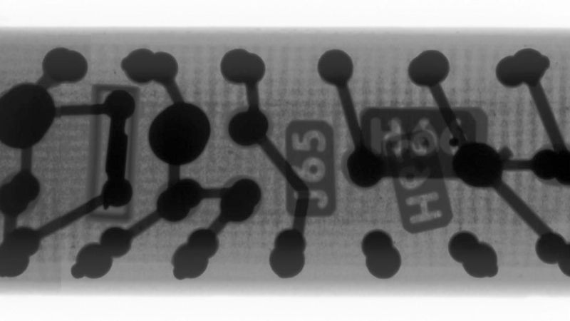
[Ken] was able to do some preliminary reverse-engineering using methods we’ve seen him employ before, but ran into a dead end with his scope and meter without documentation. So the modules went under [John McMaster]’s X-ray beam for a peek inside. They discovered that the 13-pin modules are miniature analog circuits using cordwood construction, with common discrete passives stacked vertically between parallel PCBs. The module they imaged showed clear shadows of carbon composition resistors, metal-film capacitors, and some glass-body diodes. Different angles let [Ken] figure out the circuit, which appears to be part of a square wave to sine wave converter.
The bigger mystery here is why the original designer chose this method of construction. There must still be engineers out there who worked on stuff like this, so here’s hoping they chime in on this innovative method.


A similar form of construction was used by Olivetti for it’s first generation computers. From memory the advantages were that it allowed a higher density compared to conventional construction whilst retaining ventilation. However the board were formed from a large main board with a large number of very small daughter boards in lines. Thus two main boards when mounted face to face had there daughter boards interleave. Repairs could be made by de-soldering the daughter board and replacing components and then reassembling the daughter board. Many of daughter boards were of the same design probably making manufacturer cheaper.
I’m not an engineer, just a guy who has spent way too much time up to his elbows in old Motorola equipment.
The module construction style shown in the photo here and on the linked page was common on Motorola equipment in the 1970s, and probably earlier.
The MX300 from 1975 used many such plugin analog modules.
https://radiohistory.uk/MotorolaMX300.htm
The particular modules may have been standard modules or may have been developed specifically for the Apollo project – I don’t know.
What’s sure is that Motorola used a lot of such modules back in the day.
The engineers who designed and built that test equipment were simply using the construction techniques that they used on a daily basis.
I’m pretty sure I saw some of those modules in scrap electronics I busted up in the 80s. It would’ve been stuff from Fermilab surplus auctions; so Motorola prototyping gear would’ve been easy and normal for them to be using.
He is absolutely incredible at reverse engineering extremely complex electronics. Watch him, Marc and the rest of the team do all kinds of fascinating stuff with Apollo Program electronics they reverse engineer, repair and calibrate as needed on the Curious Marc YouTube channel:
https://www.youtube.com/c/CuriousMarc/videos
Modules like these were pretty common in the 60’s and 70’s where it mimimized assembly and increased durability. I had a field trip in college to the Sprague Electonics plant where they made modules like these, most of which were embedded in a ceramic coating on a substrate, and the presenter took us by a big bucket of TiO2 substrates which were chipped and mis-shapen and gave us all samples, saying it was only X units of hardness away from diamonds.
We then went to a manufacturer of high powered electrical switchgear where they were showing off their indestructable epoxy electrical panel paint process, handing us a hammer to see if we could dent the panel or chip the paint and asked us if we had a pocket knife or anything we might have to attempt to scratch or chip the paint. I asked if they were sure and …………
Sounded like finger nails on a chalkboard as it neatly peeled off the paint.
I *have* quit doing things like that.
Years ago I saw a video taken at an electronics trade show. A company was demonstrating their new super tough phone. The rep handed one to the guy interviewing him and told him to try anything. Anything was whanging the display side onto the edge of the metal framed water tank they’d used to demonstrate the phone was waterproof. It did take 3 or 4 hard hits to crack it. The company guy said “I did say anything.”.
Cordwood construction was quite common in computers and high end electronics of the 1960, and pervasive throughout the Apollo spacecraft. It is much more expensive and difficult to repair, but far denser than regular flat PCB construction and more reliable (you can weld it). The exception being the 7 layers (!) PCB construction in the Apollo Guidance Computer logic modules, with surface mount (!) ICs welded (!) on it. However the analog modules, for the core memory and the power supplies for example, are cordwood with components embedded through a slab of aluminum.
In the 60s I earned an electronics merit badge from a guy who had some unpotted cordwood modules that were purportedly temperature sensors for the Apollo spacecraft.
I worked for a Motorola 2-way radio shop in the 80s where we saw stuff from back into the 60s and I don’t recall seeing any cordwood modules. I do remember seeing a radio with a flex circuit board like the MX300 linked to in another post. Not sure it was the same radio but the one that showed up defied troubleshooting on the bench as things had to be unplugged to unfold it and access all the components. In our part of the world bricks like the HT220 with their conventional circuit boards were the coin of the realm.
I have made my own cordwood module using small squares of verboard or perfboard I find that small modules can be made this way that make up circuit blocks I have used them in various projects to save space I fit and parts on the veroboard squares and fit wire ended resistors vertical to make multi layer modules you can cover them in conformal coating to protect them a sort of home made integrated circuit