Amateur radio operators have played a longstanding game of “Will It Antenna?” If there’s something even marginally conductive and remotely resonant, a ham has probably tried to make an antenna out of it. Some of these expedient antennas actually turn out to be surprisingly effective, but as we can see from this in-depth analysis of the characteristics of tape measure antennas, a lot of that is probably down to luck.
At first glance, tape measure antennas seem to have a lot going for them (just for clarification, most tape measure antennas use only the spring steel blade of a tape measure, not the case or retraction mechanism — although we have seen that done.) Tape measures can be rolled up or folded down for storage, and they’ll spring back out when released to form a stiff, mostly self-supporting structure.
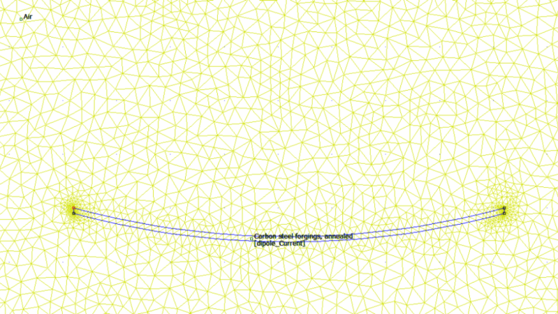
But [fvfilippetti] suspected that tape measures might have some electrical drawbacks, thanks to the skin effect. That’s the tendency for current to flow on the outside of a conductor, which at lower frequencies on conductors with a round cross-section turns out to be not a huge problem. But in a thin, rectangular conductor, a little finite element method magnetics (FEMM) analysis revealed that most of the current is carried in very small areas, resulting in high electrical resistance — an order of magnitude greater than a round conductor. Add in the high permittivity of the carbon steel material of the blade, and you end up something more like what [fvfilippetti] calls “a tape measure dummy load.
One possible solution: stripping the paint off the blade and copper plating it. It’s not clear if this was tried; we’d think it would be difficult to accomplish, but not impossible — and surely worth a try.


I believe “at higher frequencies” fits better here.
At higher frequencies, the skin effect very much becomes a problem on round conductors too.
Indeed. I missed the “not”.
The so-called skin effect is based upon a misconception of how electricity actually works. It does not flow through a material electricity actually is conveyed as a magnetic field. The skin effect is due to less efficient coupling.
See the word ‘not’ tucked in there? Technically correct but I’ll admit it tripped me up on first read, too
The most popular VHF/UHF “tactical” antennas are basically the same thing – a slightly coated tape measure with a loading coil.
The bush whip halves the effective range though.
Indeed. I missed the “not”.
So what’s the actual deal with it, at ‘high’ frequencies? You’d think a flat tape, having a much larger surface to interior ratio, would suffer less from skin effects than an equivalent weight round conductor. Unless the current gets pushed to the very edges of the tape?
* meant to also ask, does the effect manifest mainly at VHF, or was it objectionable at, say, 40m?
The main benefit of this type of antenna, is that you can extend it and it’ll stay upright by itself when used on VHF and UHF.
At 40m, this antenna would not be very useful because the tape doesn’t stay upright when extended to 10 meter, and the resistive losses would skyrocket. You would probably be better off with a simple spool of wire, perhaps with a crank.
Although now i am thinking about it, it might be a useful way to make a highly portable magloop antenna. The issue of having a big resistance has to be solved. Especially in magloops, even on low power you can have multiple amps flowing in some parts of the loop. A copper coating might just burn off, though it’s worth a try.
Maybe YOUR tape measure doesn’t stand up at 33 feet
*Stares in Stanley FatMax*
there is actually a commercial antenna which is based on a tape measure, but motorized. so you can have a dipole or vertical for any band. the tuning uses no marching network: it extends or retracts the radiator inside a fibreglass tube.
I don’t think it’s the geometry. As you mention, ribbon conductors are actually helpful due to the increased surface area relative to the overall volume. I think it’s primarily just the fact that it’s steel. The higher permability alone would effectively reduce the skin depth by ~30, and then tack on the low conductivity (another factor of 10-15) and the overall resistance is just crazy.
In the article, yes, you’ll notice in the second simulation (after copper plating) while the current *density* is highest at the edges, it’s not that much higher, like a factor of 4. And considering the edges are only probably like ~0.1 mm while the width is probably 10 mm, the majority of the current ends up being carried on the body of the tape.
So for the TL;DR folks: technically the current density is highest at the edges, but that’s a negligible effect because of the negligible overall area.
Check out the big flat elements on this satcomm antenna (Trivac-Avant AV2040-2) I’d love to know more about it. https://i.ebayimg.com/images/g/unEAAOSwqdJiqihr/s-l1600.jpg
@Bob Coggeshall said: “Check out the big flat elements on this satcomm antenna (Trivac-Avant AV2040-2) I’d love to know more about it. https://i.ebayimg.com/images/g/unEAAOSwqdJiqihr/s-l1600.jpg”
That’s a Trivec Avant SATCOM antenna 9.0 dBic 240-400 Mhz 200W Model AV 2040-2.[1] It is a UHF-MilSatCom [2] portable/field antenna. The “tape measure” elements are self supporting when unpacked. The large flat elements may increase bandwidth. The bent-pipe UHF MilSatCom satellite transponders are notorious for being occupied by illegal bootleggers. That’s why so many roll-up field deployable antennas like this are sold on the web.
1. Trivec Avant AV 2040-2 SATCOM Antenna
https://www.american-milspec.com/p-6375-trivec-avant-satcom-antenna-90-dbic-240-400-mhz-200w-av-2040-2-with-pack.aspx
2. UHF-MILSATCOM
https://wiki.radioreference.com/index.php/UHF-MILSATCOM
There’s a satellite in space with one. A guy in a shed from Wales, has one up there. Bought the antenna at pound land.
A lot of satellites have tape measure antennas. In fact, it might have been satellites that first used them. It’s a way of getting an antenna into a small package when rolled up, then have them reliably deploy as all you have to do it let them ping out and unfurl themselves.
Interesting to hear that the source for at least one of them is Poundland!
The Sony Tick-Talk talking clock/FM AM Radio has one of those style antennas, it’s neat.
There was a time when no telescoping antenna was safe from my toddler.
B^(
When I was seven, I got a pair of cheap walkie talkies. Soon someone in the neighborhood broke the antenna by leaning on it. Oddly, my father was able to get a single walkie talkie that matched. They usually came in pairs.
Maybe it was the same kid who broke my Mattel camouflaged submachine gun. That too I’d had a short time, same sort of breakage. Though it could be glued back together.
I wonder how useful the tape would be as a reflector, instead, with the actual antenna wire run up the concave side.
That would only work with 1/2 wavelength spacing between the antenna and the reflector.
It was good enough to use for building the old OSCARS satellites, eventually that stopped but it was the best tool for the job when you needed a self deploying antenna, especially back when 10m (between low VHF and high HF) on amateur radio satellites was still a thing. I think it was a story in the ARRL magazine in the 80s, it also talked about a DIY plastic sheeting cleanroom with a HEPA filter vacuum positive pressure air system.to keep dust out. I wish I could even remember which satellite so I could search the article.
Swarm is still using them on their microsatellites.
So Oscar six, 2m up, 10M down. Went up in the fall of 1972, so almost fifty years ago. The first long life ham satellite, though I’m not sure they expected that life.
Before that, they’d been short life, so using 10M didn’t bother much. But for long term, it changed. And using 2M and 432 made antennas smaller, important for the earth end..
I seem to recall a picture in an ARRL handbook from decades past where a picture of Australis OSCAR 5 had a tape measure antenna. They didn’t even bother to remove the markings.
Dumb question:
If you increased the curvature so that it was much more tube shaped, would that fix the skin effect issue with the outer edges?
I don’t think copper coating would help much, since I expect the copper would not survive well (this is assuming that you are rolling and unrolling it for portability). But, IDK, I don’t have any experience with copper coated spring steel.
Copper, aluminum, silver, zinc, brass, etc. versus steel will beat out the geometry any day of the week. The skin depth for any iron-based (well, except austenite) material’s just terrible, the eddy currents are massive. And austenite’s got a worse conductivity so it’s just still bad overall.
For reference pure iron at 500 MHz has a skin depth of like 0.5 microns. 500 nanometers. Solder, which has a similar (actually worse) conductance, has a skin depth of nearly 10 microns, or an impedance over 20x lower.
At first I was surprised to read this because tape measures work great for building the elements of a direction finding antenna.
But then again, high resistance could be a benefit there as when you get closer to the transmitter it can get harder to find the direction because the strong signal appears to come from everywhere. Often the last 100 yards or so are accomplished using no antenna at all and one’s own body as a reflector.
“which at lower frequencies on conductors with a round cross-section turns out to be not a huge problem. But in a thin, rectangular conductor, a little finite element method magnetics (FEMM) analysis revealed that most of the current is carried in very small areas, resulting in high electrical resistance — an order of magnitude greater than a round conductor”
As I mentioned above, this is wrong. The problem isn’t the geometry. Flat, thin conductors are better by weight for antennas. Focusing on the “edges” here is pointless, it’s only a factor of 5-10 in terms of *current density* and the overall area of the edges compared to the rest of the tape is what, 1%. So the majority of the current isn’t carried at the edges, it’s carried across the tape.
You can see this in the second simulation where now you can see the tape carrying current. Yeah, the edges have higher current density. Doesn’t matter, they’re negligible area.
The problem is just the conductor. Any magnetic metal is *terrible* for an antenna conductor at high frequencies: the skin depth just drops to nothing.
As is noted in the article, after plating with copper the overall impedance dropped by a factor of ~8 or so, which is exactly what you’d expect swapping from, say, iron to copper.
sorry, should’ve just said thin conductors. Flat vs a round thin tube doesn’t really matter.
Pat: I upload all simulation files so you can make a simulation of a round conductor of the same area and compare ac resistance with the tape measure. Common wisdoms of a “superficial conductivity” is wrong here and is exactly the thing that needs a finite element simulation, because analytical solution is not possible as is in round conductor. so i really like to view a femm simulated comparison to prove me i am wrong.
As far as unique “antennas”, after buying a VHF antenna tuner a friend and I loaded up an aluminum ladder, a table saw, and a garage door (swing-up type) and worked a repeater 65 miles away, with respectable receive quality. The goal of the test was to make sure it would work for our actual use, which was to load up a roadside emergency phone mounting post during a T-hunt. It worked great, and there was much confusion. :)
So in that spirit, remember a commonly promoted use for the tape measure antennas: crashing through the brush during an on-foot (or in the last 100 yards of a mobile) hunt, avoid the damage that can be caused to the antenna or the person carrying it if using a fixed-radiator Yagi. While you technically can transmit into them, they are meant for receiving duties, and a few or a dozen dB of attenuation added due to resistance of the elements is not a bad thing for this application.
I made a 2m Tape measure antenna for Direction Finding, and it worked better than a $150 Arrow antenna a friend of mine used.
http://www.k4hsm.com/2010/09/my-2m-tape-measure-antenna-project.html
I Was bored once and used a steel lamp post high on the mountain for CB radio, of course had a match meter and adjusted a bit. Next think I know I’m talking to people who think I’m next door but was actually north of them in a different country.
Another time we thew the antena in the ocean to see what happens…