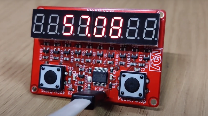
[MakingDevices] has created a simple stopwatch that makes for a nice introduction to surface mount electronic design and assembly. The project is open source hardware (OSHW) certified, with Gerbers, KiCAD files, and software all available.
Conceptually the stopwatch is straight forward, with a row of two four digit seven-segment displays being driven by a PIC18LF14k50 microcontroller through multiple NPN transistors. The PIC doesn’t quite have enough data lines to drive the two displays at once so an inverter is used to toggle between the two seven-segment blocks.
The circuit is continuously powered from a CR2032 coin cell battery. For normal usage with display, [MakingDevices] estimates 30+ hours of operation and 140+ hours without display, but still counting time. When idle, the “Extreme Low-Power (XLP)” capabilities of the PIC put the operating window estimates well beyond the self discharge of the coin cell battery. There’s an in circuit serial programming (ICSP) footprint that accepts a pogo pin TC2030-MCP-NL adapter for flashing the PIC.
Don’t let the simplicity fool you, this is a well documented project with detailed posts about the design, simulation and battery consumption. Various videos and glamour shots give a whole picture of the process, from design, assembly, testing to final validation.
It’d be wonderful to see the project extended or hacked on further, perhaps with a cute enclosure or case.


The PIC18LF14k50 is getting scarce. Mouser has only 196 in stock at qty.-1 $2.76 each and more than a year lead time. A measly 335 are expected on 10-Oct-2023.
https://www.mouser.com/ProductDetail/Microchip-Technology/PIC18LF14K50-I-SS?qs=WqWCsLCZBko9m2LqZWTYcA%3D%3D
PIC18 is a terrible chip for an OSHW project. The SDCC port is entirely unmaintained. Go with an ATtiny.
Sleep power consumption is pretty high, it is measured at 258uA which is 38 days if I am not mistaken with the CR2032 data given on the website (energizer, 235mAh to 2V which must be the cutoff voltage of the PIC). The 100+ years battery life estimate given must be a mistake. It might be worth trying to see where this current is going as the PIC core is probably only taking a few undred nano amps. Maybe have a look at how the GPIOs are configured before entering sleep mode, if their configuration is not changed they retain their state.
PIC18 ??!? No, thanks :-)
I obviously love the choice of kicad, and both hardware/software being opensource (even the *-bak !)
I think the inverter could be avoided by using a PNP transistor for C_display.
If energy is such an important point, why use a cr2032 ? Use a lipo such as a 18650 with a nice holder under the pcb.
The inner maker/engineer inside me is not convinced at all by the justification for quick¬-so-expensive 4-layer. And i’m not know for being especially meticulous or nitpicker.