A problem which beset early telephone engineers was that as the length of their lines increased, so did the distortion of whatever signal they wanted to transmit. This was corrected once they had gained an understanding of the capacitance and inductance of a long cable. The same effects hamper attempts to place microphones on long lines, and [Leo’s Bag of Tricks] has a solution for doing that using Cat5 cable. The application is audio surveillance, but we think the technique is useful enough to have application elsewhere.
The solution which you can see in the video below the break will be familiar to teletype aficionados who have encountered current loops, in that it creates an analogue current loop. There is a standing DC current in the tens of miliamperes, and this has the audio imposed upon it by an amplifier and shunt transistor. The audio can be easily retrieved using a pair of small transformers, leading to efficient transfer over as much of a kilometer of Cat5 cable. We’re guessing it’s not quite audiophile quality, but it’s useful to know that a current loop can be just as useful in the analogue domain as in the digital. If the subject interests you, we did a feature on them a few years ago.


ANd to those that bemoan that the lowly 4-20mA current loop is limited to one device or only one channel of information, I suggest you google the HART protocol, which allows you to parallel multiple devices and/or access multiple types of information over a single 4-20mA loop by using a 1200 baud, half duplex modem protocol which puts an analog carrier on top of the current loop – bragging a little, back around 2000 I had a software modem, 4-20 loop measuring device, multi-threaded software unit that all ran in a PIC14000 with just 2K words of software.
Interesting
Current loops were also used for interfacing terminals with mainframe computers Because they used only two signal levels, it was easier to achieve long range communications. Some time ago I wrote an article about my idea for making a modern version of that system for hobbyists:
https://www-elektroda-pl.translate.goog/rtvforum/topic3881307.html?_x_tr_sl=pl&_x_tr_tl=en&_x_tr_hl=pl&_x_tr_pto=wapp
RS-232 also uses only 2 signal levels. Some mainframes (e.g. those from Tandem) used current loop primarily because it rejects common mode noise to a very high degree even without shielded cables, and because it simplifies the power supply requirements. Current loop terminals always used software handshaking (ENQ/ACK or XON/XOFF commonly) which reduced the number of wires required compared to hardware handshaking (although terminals using RS-232 also commonly supported software handshaking).
Cat5 works great for balanced audio aka “pro” audio, even balanced microphones, and is why there’s a “Studio Hub” standard for it, and tons of cheap Cat5 snakes on Amazon — no special interfaces required. Many radio stations have tons/miles of it and a bunch of 66 punch blocks. At long-enough lengths, transmission-line reactance affects sound quality (which the phone company’s dealt with for a looong time), and there’s increased need for galvanic isolation (transformers, whether Ethernet or audio) and surge-protection devices.
Very nice 4 twisted pairs. Run it in differential mode with impedance matching and it will be quiet. The specs on cat5 are pretty tight.
I thought I invented that use. I didn’t know pros were using it.
Oh well.
Yes, you can run 4 channels of balanced audio over Cat6. You can even get phantom power, but it requires EtherCon connectors and a shielded cable with the ground connected on both ends.
While this method is indeed effective for transmitting sound at long distances minimizing common mode noise and interference, it doesn’t solve the problems created by wire inductance and capacitance. An effective workaround would be to send a higher frequency carrier modulated by the original signal, which wouldn’t be hard since network cables are designed for very high frequencies.
If you have an inductance issue for your wires, then you’ll have hard time transmitting high frequency signal through them.
The cat 5 cable or coaxial or even uniform parallel lines ,form transmission lines and the engineering is long understood..the parallel capacitance and the series inductance set up the characteristic impedance . So its not a problem… .
The advantage of a current loop , and why it was always preferable in a control system is that it is immune to voltage induced interference, because its impedance is so low. Moreover it was isolated from system ground and therefore was differential in mode. The RS232 voltage systems were susceptible , because they were referenced to a ground. The slightly later RS442 standard removed the ground reference and improved signal integrity
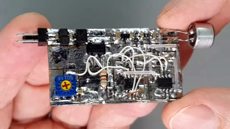
I saw that PCB and immediately knew who made it, it’s a trademark. Leo is great! And BTW he has a video on YT on how to make them that is actually commented by Elliot Williams himself.
Is this implementation better than a standard phantom power microphone setup?
It uses only 2 wires. Phantom power requires 3.
It produces up to 5Vpp, or (say) +15 dBm signal. An unamplified mic tops out around -40 dBm. If they are both subject to the same noise floor (like -120 dBm), this setup would yield a 55 dB better dynamic range. Single he’s not shielded and his common mode rejection isn’t so good, it’s probably not achieving all that 55 dB, but it’s still going to have a whackload more dynamic range.
Add a shield and pay good attention to common mode rejection, and this setup could achieve 135+ dB (23 bit) dynamic range.
Unamplified mic-level phantom power setups don’t typically match line impedance, so aren’t really intended for long runs. Whether [Leo] deliberately designed it that way, or whether he was just dumb lucky is hard to tell, but his system matches Cat5’s 100-ohm line impedance pretty well, and that’s the key to long runs.
With that 2 transformer arrangement, I bet common-mode rejection is actually pretty respectable.
Normally I hate single-Utube-link projects. But I gave this one a chance, and once he got into the circuit description… I was impressed. Clever engineering and well presented.
The current loop aspect isn’t the reason why this design works to over 1 km. You get that range by amplifying mic level up to line level, and then having a really low impedance output driver to overpower line reactance. The current-loop neatly solves the additional problem of remotely powering the electret mic and the mic preamp/line driver, and all over just one pair of wires.
The word for this solution is… elegant. Simple, robust, high-quality. it was worth the watch. Thanks.
uhhmm… you don’t “overpower line reactance” to get range. You don’t win this game by brute force. You want to match the line impedance (at both ends) to launch a propagating signal down the line with no reflections off the impedance mismatches.
For extra bonus points on really long lines, you also want to satisfy the Heaviside Condition, to minimize dispersion. But that’s a property of the line, not its transmitter or receiver circuits.
Driving high power lets you keep a healthy margin above the thermal noise floor, but that’s a different issue.
The impedance of a cat5 pair is ~100 ohms; this project runs close to that. You’re correct about the importance of matching. The wavelength of a 20kHz sinewave in twisted pair is roughly 10 km, so reflections in just 1.2 km or less… not really an issue here, right?
One thing I failed to acknowledge – there’s feedback on the current sink, which also helps compensate for path reactance. Elegant, the whole thing.
I think the current loop provides some inherent immunity from EMI that you don’t necessarily get with “line level” audio. If you have a high impedance load on the other end, a voltage signal is going to be very sensitive to noise. If you have a low impedance load on the other end, then it seems like there’s little practical difference between line level or a current loop, other than whether or not the volume decreases with distance due to voltage drop over the wire. Whether you’re using current or voltage to encode the audio signal, you can have a bias to provide power, and you would need to remove it before feeding the sound into a loudspeaker.
On my backlog of hobby projects is to build a 4-20mA microphone array. I want to have 8-16 of them to do beam forming for noise suppression, in an EMI hostile and space constrained environment.
High end industrial motors often use a two wire interface for position feedback for commutation, over tens of meters. There’s a DC voltage across the wires to power a microcontroller on the motor end, and several Mbps serial data is modulated on top of it. It’s very sensitive to EMI, which necessitates shielded harnesses.
A normal analog microphone can go OK through a kilometer of Cat5 cable. Audio “mythbuster” Dave Rat lets you to listen to what Shure SM58 and a Neumann U89 sound like when run analog down a mile and a half of Cat5e cable in tjhis video
https://www.youtube.com/watch?v=f0nKK43Oeas
Haven’t watched the video yet but it sounds like the commercial 100v line system. https://www.redbackaudio.com.au/understanding-100v-line-distributed-speaker-systems/
I jus built and sold a laboratory pressure measurement system using curret loop. It was the most reliable way to send signal through a rf noisy hall full of machinery.
Current loop is old, but not dead.
I guess I’m getting old or electronics 101 isn’t being taught in college anymore.
1. Running DC current down twisted pair has *absolutely* no impact to the audio noise level on the lines.
2. This is a Rube Goldberg answer to the question of just how many parts can we use to solve a simple problem.
3. It’s no problem *at all* to run 20Hz to 20 KHz 60 dB s/nr audio down 10 miles of wire on properly compensated pair using 0.775 v audio (0 dBm at 600 ohm).
Used to do it all the time with unshielded 50 pair (untwisted and unbalanced) scuzzy and nasty dry pair Telco phone lines that probably ran through 10 punchdown junction boxes and buried vaults and 2 central offices along the way and do a full freq response, distortion and signal to noise proof of performance annually as stereo studio to transmitter links back in the day. (and sometimes football feeds in the next town over)
It’s probably a bigger issue to run DC because of the resistance of the wire but that shouldn’t be an issue with CAT (X) cable.
I can think of using maybe 1 or 2 transistors, a couple of resistors, capacitors, transformers and an electret mic to do the whole thing.
Sorry for the attitude but I’m constantly amazed with engineers I know who can’t run audio across the room without hum, noise and distortion. It must be a lost art. And it’s so simple.