The Serial Peripheral Interface (SPI) interface was initially standardized by Motorola in 1979 for short-distance communication in embedded systems. In its most common four-wire configuration, full-duplex data transfer is possible on the two data (MOSI, MISO) lines with data rates well exceeding 10 Mb/s. This makes SPI suitable for high-bandwidth, full-duplex applications like SD storage cards and large resolution, high-refresh displays.
STM32 devices come with a variable number of SPI peripherals, two in the F042 at 18 Mb/s and five in the F411. Across the STM32 families, the SPI peripheral is relatively similar, with fairly minor differences in the register layout. In this article we’ll look at configuring an SPI peripheral in master mode.
Defining SPI
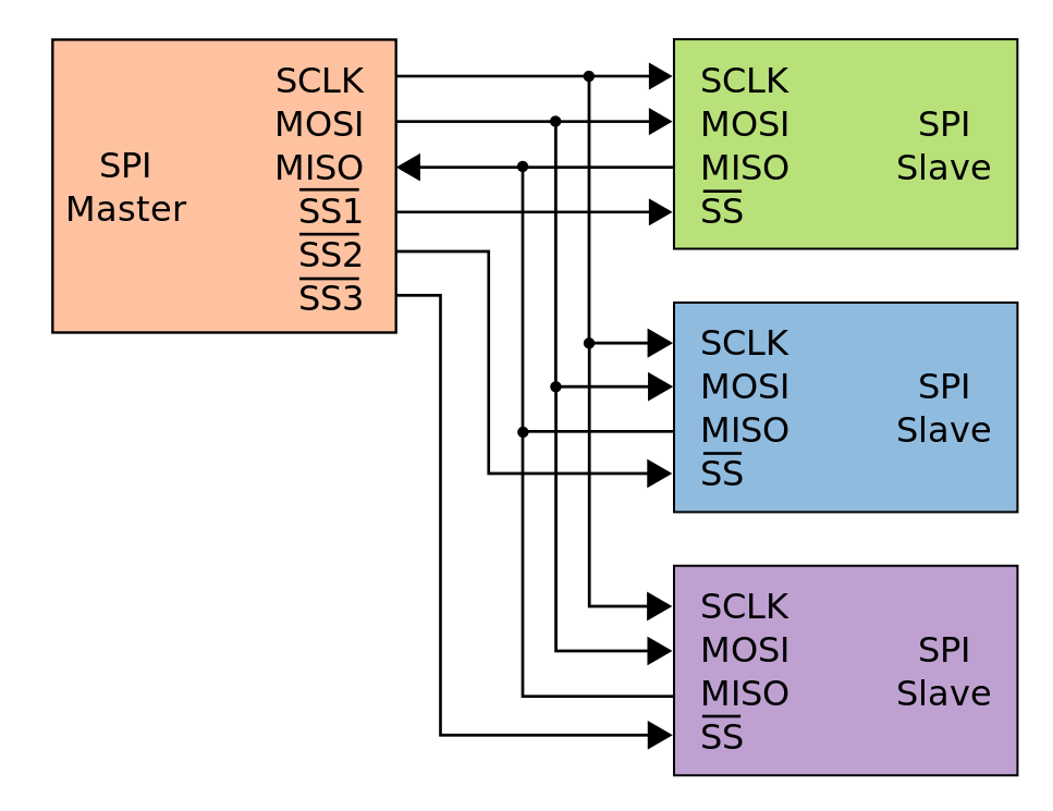
One interesting and perhaps annoying factoid with SPI is that although it can support multiple devices, it does not have an addressing bus, but instead requires that a designated pin is pulled low on the device, usually called slave select (SS) or chip select (CS). With SS high, the slave device puts its other pins into high impedance mode, effectively disconnecting from the SPI lines. The STM32 SPI peripherals have a provision for a dedicated SS pin (NSS) that can streamline this process if only one device is connected. Generally you want to use GPIO pins to toggle these SS pins, with one GPIO pin per device.
For four-wire SPI the master and slave devices are thus connected with the following lines, with the SS line duplicated for each additional slave:
- SCLK (serial clock, from master)
- MOSI (master out, slave in)
- MISO (master in, slave out)
- SS (slave select)

Setting up the SPI peripheral is relatively straightforward, requiring the configuration of the clock and parameters such as 8- or 16-bit transfers. Less obvious are the SPI clock polarity (CPOL) and phase (CPHA) parameters. Here the default (Mode 0) is usually CPOL 0 and CPHA 0, which translates to the clock line idling low and new data being pushed onto the data line on the trailing edge of the current clock cycle. CPOL 1 and CPHA 1 result in the opposite behavior. Slaves may support modes other than mode 0, but the datasheet for each slave has to be consulted on a case-by-case basis.
With all of this in mind, we can look at configuring SPI on both the F411 and F042 microcontrollers. Due to the aforementioned similarity between the SPI peripherals across the STM32 families it’s relatively straightforward to adapt the initialization routine. The data transfer routines themselves remain unchanged.
Setting Things Up
Setting up an SPI master begins with configuring the GPIO pins that we’ll be using. This involves setting the appropriate Alternate Function (AF) mode and pin parameters, for example AF5 on the F411 MCU’s pins 4 through 6 on port A. The SPI pins themselves are assigned the following properties:
- SCLK: floating, push-pull, high speed.
- MOSI: floating, push-pull, high speed.
- MISO: pull-up, push-pull, high speed.
- SS: pull-up, push-pull, high speed.
Since SPI relies on a push-pull configuration rather than the open-drain of I2C, we have to set all pins to match this, along with the fast GPIO speed option to keep up with the SPI signaling. The decision to leave a pin floating versus activating its pull-up is determined primarily by the function of these pins. In the case of a select pin it is essential to keep it in a high state in order to prevent accidental activation of a device before the system has finished initializing.
Activating the MISO pin’s pull-up is done to keep this line in a known state when no devices are selected and thus none of them are driving the MISO line. Even though the master is not reading the incoming data register, the intermediate voltages can potentially cause issues like excessive power draw.
With the GPIO pins thus configured, the target SPI peripheral is enabled in the relevant Reset and Clock Control (RCC) enable register. For example, the SPI 1 peripheral is enabled in the RCC_APB2ENR register, while SPI 2 and SPI 3 are generally found on the APB1 bus and thus enabled in the corresponding register in RCC. Next up is configuring the SPI peripheral itself.
The first item to configure here is the SPI clock divider (baud rate, BR) in the SPI_CR1 register. This uses the APB frequency (the peripheral bus frequency, or fPCLK) as the input for the SPI clock, which can be set to between fPCLK/2 and fPCLK/256 using three bits of resolution. The divider should be picked to achieve a reasonable clock and thus transfer speed for the application.
While on both the F0 and F4 families the default transfer size is 8-bit, the latter’s peripheral only allows for setting the data frame format to either 8- 16-bit in the SPI_CR1 DFF (Data Frame Format) register. With the F0’s SPI peripheral the range of options is far larger when configuring its DS (Data Size) value in the SPI_CR2 register. This is a 4-bit value that allows for the data size to be configured to anywhere between 4- and 16-bits, with e.g. 8-bit corresponding to b0111.
Unless there are special requirements, the default 8-bit data size, default Mode 0 configuration and default MSB-first setting are good default choices that should work with most SPI devices. This then means that only the clock divisor has to be configured in all cases, after which master mode can be enabled in SPI_CR1 (MSTR). The SS pin can then be enabled and set as output by setting SSOE in SPI_CR2.
Finally, the SPI peripheral can be enabled by setting SPE (SPI Peripheral Enable) in SPI_CR1.
Data Transfers
As mentioned earlier, SPI allows for full-duplex transfers. The complication this adds comes from the fully synchronous nature of SPI: for every byte put on the MOSI line by the master, the slave will put a byte on the MISO line, and vice versa. Since the clock line is driven by bytes sent by the master, the result is that in order to receive data from a slave, the master has to put data (e.g. null bytes) on MOSI for each byte on MISO.
A way around this is by changing the SPI bus from a four-wire to a three-wire (half-duplex) configuration using BIDIMODE in SPI_CR1, which does require cumbersome reconfiguring of the peripheral in between transfers. Generally you would want to just put null bytes on MOSI to save yourself this trouble.
In order to send bytes to a slave we thus follow this sequence after pulling the target’s SS line low:
- Wait for
SPI_SR_TXE(status register: transmit register empty) to become true. - Write data (8-16 bits) into
SPI_DR. Repeat from (1) if more data has to be written. - Wait for
SPI_SR_TXEto become true again. - Wait for
SPI_SR_BSY(status register: bus busy) to become false.
The sequence is ended by pulling SS high again, although noting that some SPI slaves support multiple writes in a single sequence. One gotcha in this sequence is when we write data to SPI_DR that is <16 bits: even if we write an 8-bit uint8_t variable or similar to this register, it’ll always end up writing 16 bits into the register, with our data plus this padding put onto MOSI and ruining the data transfer. To get around this, we must cast the SPI_DR register to the intended size, e.g. for an 8-bit data array:
*((volatile uint8_t*) &(SPI1->DR)) = data[i];
In order to receive from a slave we either pull SS low, or left it low after a previous transmission sequence and follow this sequence:
- Wait for
SPI_SR_BSYto become false. - Write dummy data (e.g. 0x00) into
SPI_DRto generate a clock signal. - Wait for
SPI_SR_RXNE(status register: receive data register not empty) to become true. - Read data from
SPI_DRinto local buffer. Return to (1) to receive additional data. - Wait for
SPI_SR_BSYto come false.
Here too the sequence is ended by pulling SS high again. Note that writing the dummy data faces the same gotcha as with sending data. Ensure that the SPI_DR register is cast appropriately before writing the data. As for why we’re both reading and writing SPI_DR is because it is a shared register, connected to the SPI peripheral’s TX and RX FIFOs.
Finally, in order to perform a full duplex transceive operation, we can combine these two sequences, submitting data instead of dummy bytes while simultaneously receiving data from a slave. This is of course an operation that has to be supported by the slave device in question. For many common SPI devices and sensors most operations will likely be performed in a half-duplex manner.
Wrapping Up
There’s still a lot more to SPI as hinted at earlier, though many of the configuration options are rather obscure and rarely used, like LSB-first as well as 16-bit transfers, TI mode and the various clock phase and polarity settings. A more commonly used aspect of SPI peripherals which we will address in an upcoming article is the I2S mode that is found on most STM32 MCUs. This is a connection interface for external audio codecs, often found as secondary mode on SPI peripherals.
SPI itself sees significant use with larger-resolution displays and data storage, but many sensors like Bosch’s BME280 and related MEMS sensors also implement an SPI interface in addition to the I2C one. Depending on the system, putting some of these devices on SPI rather than I2C may make a lot of sense due to routing or other constraints.


STM32 USART devices can also be used as SPI master.
Instead of using the ugly cast to write a byte, I just modified the SPI_TypeDef struct.
Where it says:
__IO uint32_t DR; /*!< SPI data register, Address offset: 0x0C */
replace it with
union {
__IO uint32_t DR;
__IO uint8_t DR8;
}; /*!DR8 for byte access.
Ugly? Is code-shaming a thing now?
Have you considered the effect this has on the volatile keyword and where you would place it in your union construct?
A cast is a perfectly legitimate construct, especially in the world of embedded systems and microcontrollers.
“…. volatile keyword …” How about providing an example and explanation rather than just mocking somebody who posted an actual useful code snip-it?
Also: s/perfectly legitimate/often necessary/
I won’t say casting is ugly, but it’s usually a “code smell”, and avoid it usually results in cleaner code.
It’s not about shaming. It’s about readability and avoiding errors. The result is that you can replace this:
*((volatile uint8_t*) &(SPI1->DR)) = data[i];
with
SPI1->DR8 = data[i];
Yes, I have considered the effect on the volatile keyword. That’s what the “__IO” is for, just like in the original code. And when you put it in the struct, you no longer need it in the code, and you can’t forget it.
Yet, it’s undefined behavior here. When you write to a union type, if one of the member is smaller than the other, the compiler is free to do what it want with the unused space. So it can decide to use “write 8 bit” instruction without clearing the high nibble/word. You aren’t supposed to read a member different than the last one you’ve written (undefined behavior). So mixing usage of the enum is a risk too (say one part of the code writes to DR the other to DR8, you’ll get a random value in there).
The right cast could have been:
SPI1->DR = data[i]; // Yes, no cast, since the register write is word sized anyway on ARM.
> it can decide to use “write 8 bit” instruction without clearing the high nibble/word
That’s the whole point of having the union. We want to have it use the 8 bit write, so that it will only write 8 bits out of the SPI peripheral. Mixing usage is not a problem, because these are hardware registers, so they already don’t behave as regular memory. You don’t get “a random value in there”, because it’s a write-only register.
There is a little bit of undefined behavior, but so does the original cast, because it only works on little endian targets.
Your code suggestion doesn’t work, because it results in the SPI peripheral shifting out 16 bits instead of 8, even when the data width has been configured as 8.
SPI1->DR = data[i];
Looks like author programming mcu for the first time? (No disrespect).
First of all, there’s an SPI peripheral in all STMs, you call easily set it up in cubemx ide.
Secondly, although, knowing how to do stuff through registers is must for avg and above emb.engineer, I’d certainly use HAL for the very standard functions like SPI/I2C, unless you have flash.mem.space shortage and wish to flip registers (beware of bunch of exceptions then!). ARMs are full of traps. Stepping into them every week (HAL is far from ideal too).
Not being a professional programmer myself, but with the author being the author of multiple (embedded) programming related books, among which “Hands-on Embedded Programming With C++17”, I would argue that they would at least have some clue what they’re talking about.
These series are “bare metal” STM, so attempting to be as close to the real hardware, not necessarily the easiest or most accessible way.
I would argue that since the author of this article has published multiple books on programming, among which one on embedded cpp, that they (at least) have some idea what they’re talking about.
In fact, this article is part of a series about ‘bare metal STM’ (you know, it’s in the title), so I don’t think they intended to show programming with the HAL or via CubeMX. Rather, this is a deep dive for ‘under the hood’ programming, which I for one, quite enjoy.
Admittedly I have little experience with the ST HAL, but what I remember is that it was nothing more than a thin wrapper over the bare registers. Not very useful in my opinion, but maybe I’m misremembering.
No, they have the “LL” (low-level?) variant which is a very thin register-level wrapper. Which is what I prefer, anyway.
The HAL is, at least in parts, a more bloated monstrosity that does it’s business in a, IMHO, more convoluted than necessary way. But a little more high-level, presumably more consistent over different STM32 series.
It’s a decent way to get something going quicker, with help from the CubeMX thing to do some setup & config and get some generated code.
I usually roll my own for most stuff anyway, but the HAL is a good base to start from or look at as an example.
There have been plenty of bugs over the years, though
As far as I know, the low-level library, which I also preferred, is no longer supported, so you can’t use it for newer devices (F7/H7 and such), and since the TrueStore went offline, isn’t even available for download anymore. Unless you have a copy for the specific device you want to use, or can find the library as part of an open-source project somewhere, you’re out of luck.
Lots of people don’t like using the HAL as it bloats the code a lot, hence a lot of people prefer to use the registers directly or write their own drivers for them.
Also what makes you think the author is programming MCUs for the first time? You say no disrespect but it is still very insulting, saying no disrespect doesn’t make it any less insulting. The author probably has a lot more experience than you.
Lots of people also don’t like using cubemx but you can set it to use LL drivers I think.
Also as others have pointed out this is a series about bare metal programming, not about using HAL or cubemx but about doing everything from scratch using the registers so why don’t you read what it’s about before you start complaining and insulting the author?
“The Serial Peripheral Interface (SPI) interface ”
Brought to you by The Department of Redundancy Department.
Who encourages you to check out their other fine products, including VIN number and PIN number!
SPI really shines when combined with DMA transfers; instead of waiting for each transfer (horrible practice), or handling an interrupt for each word transferred, you can just setup two buffers, one for transmitting and one for receiving, kick the DMA controller and get an interrupt when the whole transfer (which can be kilobytes) is done.
I absolutely love DMA!
Waiting for each transfer is perfectly fine if you have nothing else to do, which is the case in many applications.
Not in my world, my controllers never do just one thing, they do real-time control (power electronics and such), fieldbus communication, etc.
If by “many applications” you mean most beginner arduino-style projects, sure, but not if you’re a professional embedded systems engineer.
I’m a professional embedded engineer, yes. Of course the controllers do many things at the same time, but not necessarily at the very same microsecond. If I need to read 32 bits from an external ADC using 10 MHz SPI clock, it takes less than 4 microseconds.
Let’s say I need that ADC value 10 times per second, that’s only 0.04% CPU used. That means there’s still plenty of time to run a field bus, or do a bunch of real time stuff. I can even do hard real time things in interrupts with higher priority than the SPI transfer.
Obviously, if I do high bandwidth stuff, like a SPI network/display/camera interface, then I would set up a DMA channel for it.
I’m not very clear on why CPOL and CPHA exist even after reading the article. I understand what they do, but when would they be used? Especially after: “Slaves may support modes other than mode 0, but the datasheet for each slave has to be consulted on a case-by-case basis.” I’m left wondering why I would want to use anything other than mode 0 for either if I ever find myself programming an STM device.
You don’t, but some manufacturers have used inverted clocks or edges, and you simple need to match the device attached. The vast majority uses mode 0, just check the datasheet.
Speaking of manufacturing, are there new STM32 available to purchase? Anybody?
Shh… they don’t want to talk about that. Especially with ST Micro trying to remain relevant in light of the fact that there are no ST Micro chips anywhere, unless you count the chinese brokers who have hoarded them all.
The fun starts when you have different SPI peripherals on the same bus that use different SPI modes.
SPI is not fully standardized, so there are quite a few variations with clock phase and timing between devices from different manufacturers.
And sometimes a customer will decide for what they consider very good reasons to insist that your new part have a 10 bit or 18 bit word, and then you have to figure out how to test it to make sure it works.
Has anybody actually managed to buy any STM32s the last 2-3 years? IC shortage in general, sure, but STM32 seems to be above average unobtainable. (Talkning <100 qty from general distris, e.g. Mouser/DK here, not special-case ordering 25M+ pre-paid)
Which is a shame. I really like the STM32s.
Have not head/read ST saying anything about it either.
I get weekly emails from ST regarding webinars they are having.
I wonder why if their products are not available.
Maybe they just want to keep their engineering customers in the loop,
Or not let their webinar teams sit idle.
I would think the size of the SPI data register does not depend on any C code. If you write a 32 bit value on ly the lower N number of bits will be written into the register. If you write an 8 bit into a 16 bit register the upper byte will be zero. What is transmitted every time is the full length of the SPI register unless there is a custom setting.
No, the ARM can write bytes, halfwords, and words over the bus, and the SPI peripheral behaves differently based on that.
STM32 Spi DR is a 16 bit register. What is the status of the upper 8 bits when its memory location is cast to 8 bits and is written to?
Makes no sense to me.
IF you’ve set the frame format to 8 bits, it doesn’t matter, they never get shifted out. The peripheral shifts out the lower 8 bits then waits for the next write.
It is a dual 8 bit/16 bit register in hardware, mapped in the same address. If you write a byte, by casting the address pointer, and you’ve set the shift width = 8, then it will shift 8 bits. If you set the shift width=16, and write 16 bits, it will shift 16 bits. If you set shift width=8, and you write 16 bits, it will shift 2×8 bits in succession.
Very nice write up. Looking forward to the one on I2C.
You have to be careful with doing things yourself. Sometimes you will have errata work-arounds built into HALs that you may have to figure out. It’s probably best to compare whatever scheme you come up with against the method that the HAL uses. It’s also helpful since you can benchmark your method against it.
Very true. Plus there could be bugs/quirks in the hardware that aren’t even mentioned in the errata, because nobody has discovered them, and the HAL is just lucky to not trigger the bugs.
Stop using the legacy “slave” terminology. Despite that the pin is labeled SS make the tiny effort required to change your terminology and be a citizen of the world. If you want to keep the abbreviations call them Main and Secondary.
https://www.allaboutcircuits.com/news/how-master-slave-terminology-reexamined-in-electrical-engineering/
Or, you know, we can just put some tiny effort in not looking for new places to get offended.
I hope your comment didn’t offend him. I say HIM because Brad is generally a male name. I hope my generalization has not caused Brad grief, for my failure to use the correct pronouns… oh crap… Wait… this is Hackaday… not reddit.
Hmmmmm, I really like your technical posts.
The terms in question are genuinely triggering/offensive to a relatively small portion of our community. In a way part of the reason that the portion is so small is because few people can recognize or believe that things like this are offending people, and this in turn acts like a gatekeeper factor helping prevent our industry and community from becoming more diverse.
Another consideration is terminology impact in low maturity situations, like high school or college CS classes. Where people who don’t understand or care about the impact of their actions may feel spurred to make jokes which target their more minority class mates. (Hint: Just because it’s a joke, doesn’t stop it from being racist.) This can contribute to deterring some people from continuing their CS studies…
I’m not offend by the term master/slave, I’d bet Brad isn’t offended by them either. But we are aware that some of our colleagues (and potential future colleagues) can find this deeply offensive. Even if it seems minor to us, I’m willing to adopt new less offensive terminology.
Your: “Or, you know, we can just put some tiny effort in not looking for new places to get offended.” can also read as “Or ….. just put some tiny effort in to ignoring racism.” although I don’t think that’s what you intended.
My SPI Controller will talk to my SPI Nodes.
There was no racism here. We’re talking about electronics. Just put some tiny effort in not looking for racism where it isn’t.
Plenty of other terms are also offensive to small portions of people. The very same people that are asking for our consideration of not using master/slave do not hesitate to call others “nazi”, or “racist” at the slightest disagreement with their opinion.
I don’t believe you are being racist, and I do believe you really see no racism here. I know that whether something is racist or not to a particular individual is dependent on the sum of that person’s experiences, and everybody has a different set of experiences. If something is highly offensive to people of color (because of the color of their skin), but it’s not in the slightest bit offensive to you, that doesn’t mean there is no racism there.
The terms ‘master and slave’ are steeped deep in racism. For many it conjures up a lot history, that people with dark skin are not considered humans, not consider worthy of basic human rights, of people being forcibly kidnapped from their homes, beaten, raped, murdered, treated in a away that only prioritized maximum profit. Loaded in to a tiny space a couple of feet high between decks on a boat, crammed in as much as possible, shitting, pissing, vomiting, dying and rotting on top of each other in that tiny over crowded space, for the months long journey to be sold.
I disagree with your opinion here, but didn’t call you a “nazi” or a “racist”, neither did Brad, and I don’t see anybody else doing that either, so not sure where you are going, or coming from, with that accusation.
“Just put some tiny effort in not looking for racism where it isn’t.” But there is racism here and many people see it. Just because your life experience was different and you don’t consider this racist, doesn’t mean that it’s not offensive to others. And it could be considered a little short sighted to act like you have perfect knowledge on matter, out right deny the presence of any racism, and encourage all others to not look for racism.
This isn’t a burning cross, or a confederate flag, and compared to many other racism issues it’s rather small, but it is still an issue and it effects people in our community and industry.
Nothing “legacy” about it. Just because some people have decided to go Woke doesn’t mean the terms are invalid or inaccurate.
Secondary means not necessary, therefore misleading. A slave, instead, is necessary to the master ;)
So somebody feels sorry for the “slave” part of the interface. OK lets create new words for these. However to accurate and reflect the roles of the two entities one label needs to connotate the initiator and controller of the interaction and the other needs to connotate the passive and responsive entity. Will these new words eventually offend?
Please take you neo-woke bullshit somewhere else. SPI works like this: one device demands an action, the other device complies. Sounds like master and slave to me.
Next week, you’ll be back complaining when we can a device secondary, because all devices should be equal.
What about replacing the device select with an arbitrarily long shift register. You can save on pins at the cost of a little bit of time switching devices.
You could, but that does require a few pins in itself, because you need to have exactly one low bit in the register. A data output and clock output would suffice, you can first fill the register with all high bits, and then shift a single low bit to the desired device. You could even use the SPI MOSI signal as the data input for the shift register, since you could clock either the shift register or the SPI bus, but never both at the same time.
Hi,
Do you know how we can do dual read from an SPI flash using normal SPI peripheral instead of QSPI?
Could you please update the archive regarding this series: https://hackaday.com/series_of_posts/stm32-bootcamp/ ?
Thank you very much for everything! It’s very instructive and well explained. Congrats for the hard work here Maya!
uint16_t readADC(SPI_TypeDef *spi) {
uniadc vals;
__HAL_LOCK(_spi_handle);
ADC_CS_GPIO_Port->BRR = (uint32_t) ADC_CS_Pin;
// Dummy SPI Transfer to initiate data exchange
spi->DR = (uint16_t) 0;
// Wait for MSB to be received
while (!(spi->SR & SPI_FLAG_RXNE))
;
vals.msb = *(__IO uint8_t*) &spi->DR;
// Wait for LSB to be received
while (!(spi->SR & SPI_FLAG_RXNE))
;
vals.lsb = *(__IO uint8_t*) &spi->DR;
// Deselect ADC to end conversion
ADC_CS_GPIO_Port->BSRR = (uint32_t) ADC_CS_Pin;
__HAL_UNLOCK(_spi_handle);
// Combine MSB and LSB into a 16-bit result
return vals.value & (0xFFF);
}
I am tryung to the same thihg ias suggested by the author, but for some reason i am getting data in a wierd way, the data i am recieving (vals.value) is twice the expected value. Here i am trying to read data from a spi based adc – adcs7476.,
pls help :)
Thanks for showing how to “cast” the 16 bit DR register to 8 bits. As a programmer for decades (and a lot of that time doing Mil-standard software), that casting is not “ugly” as one person has suggested – to me it is the elegant solution I was looking for (I’m not as proficient with C as I was with Pascal and Ada). With an explanatory comment above the statement, it is clear why and what the casting is doing (much better than modifying the standard global type definitions – a riskier and less maintainable thing to do in my view)