[MirageC] is a bit of a contrarian. Instead of taking pictures of 3D printed objects that show them in their best light, he takes pictures that show them at their worst. The reason? He wanted to figure out why he was seeing a strange artifact in his printer when using a direct extruder. Just at a quick glance, you might think the problem was Z wobble, but, in this case, it was something else. You can see the fine detective work in the video below.
There were a few odd things about the problem. First, it scaled with the part size. Secondly, the problem got better when he switched to a Bowden tube setup. We don’t want to give away the ending, but you can guess from that clue that the problem had something to do with the extrusion system.
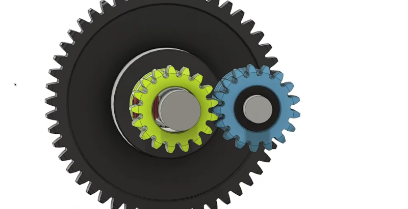
The resulting analysis led [MirageC] to work with BMG to create a special gear which — surprisingly, didn’t help as much as he thought it would. However, it did help point the way to the correct solution.
Along the way, you can learn a lot from following along, and maybe you’ll even improve the quality of your prints. We always enjoy these detailed analyses of printer issues, like the ones from [Stefan], for example. If you want to go hardcore engineering on your 3D prints, you can always do finite element analysis on your infill.


Very interesting! I sometimes print large, transparent vases and see a wood-grain pattern in the prints when the light shines through them just right. I wonder if that isn’t the same artifact of the Bondtech BMG extruder gears or filament drive teeth.
https://1.bp.blogspot.com/-kLWsRAX7f3A/YO9lGBLyv7I/AAAAAAABU8Q/KZXl4P-l8AMZPgkTnT7677zal41tgmyaQCPcBGAYYCw/s6480/07130006.jpg
I’ll be watching for the new gear sets from Bondtech.
The woodgrain pattern is analysed here: https://youtu.be/32dTLRNIYmw
Yep and his designs are awesome as well. To be fair to MirageC perhaps he never saw the video, but with over 100K views I find that a bit difficult to believe.
Eccentricity and off center holes is an issue in all pulleys and gears on a printer and often look good but are sneaky little shits. I use a laser pointer laying on a gear and shooting it across the room and back using a mirror as a quick and dirty estimation to go through bulk purchases and sort out good vs bad ones.
Can you explain this set up a bit more – having a hard time picturing it.
It’s basically what he used the dial indicator for. Although i have one and a proper magnetic base, it’s just easier to grab the pointer in my desk. Just laying a laser pointer one end on the table, one end on a motor shaft/pulley/gear (I have steppers with the shaft sizes that’d match laying around). Thin gears I might tape a folded a business card into a u shape to keep it on). Where the laser hits the wall, I’ll rig a small mirror to shoot it back against something near the motor and watch the travel of the laser. The longer the laser travels the larger the variation in movement of the laser dot. The dial indicator gives you some numbers, so I’d default to say that’s better. Still, I enjoy my quick and dirty method because lasers.
I think part of the problem is that 3D printers positioning and extrusion is mostly open-loop, which means any errors are uncorrected. Maybe if there was a reliable and accurate way to measure the mass or volume of the material being extruded? The power used by the extruder could be an indication, since the temperature is controlled closed-loop, and melting more material would require more power, but I doubt that would be accurate or fast enough to be useful.
I’d think this would be much worse if you tried to print with granular feedstock directly, or if you tried to make the filament from granular stock, considering how fairly small errors result in visible distortion.
It does seem to be a mostly esthetic issue.
His biggest issue with this is that cheaper printers don’t have this issue. A $150 bondtech is out performed (by this metric) by a $10 clone.
It’s not difficult to get a close approximation of the extruded material mass using a smart filament sensor.
IDK, LMGTFY,
They’re a record company aren’t they? Teamed up with Sony? Sony-BMG? Or am I misremembering it?
That was what I was going to write.
I thought it was Browning Machine Gun, as in .50BMG.
… sounds like what Sony-BMG aimed at their foot when they released those root-kit infected audio CDs…