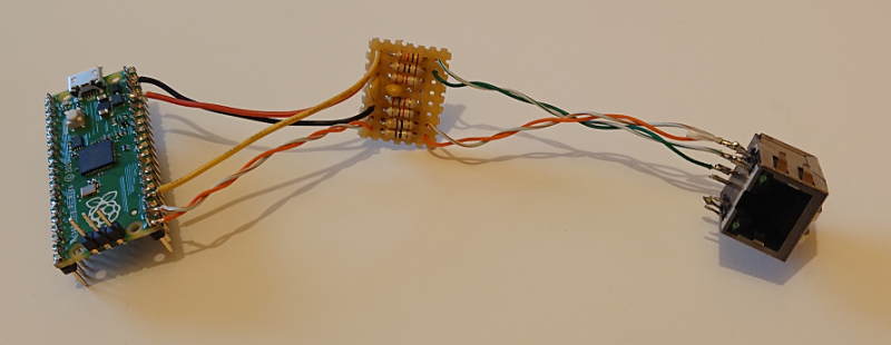
These days, even really cheap microcontroller boards have options that will give you Ethernet or WiFi access. But what if you have a Raspberry Pi Pico board and you really want to MacGyver yourself a network connection? You could do worse than check out this project by [holysnippet] that gives you a bit-banged bidirectional Ethernet port using only scrap passive components and software.
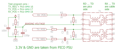
This project is similar to one we shared back in August by [kingyo], but differs in that what [holysnippet] has achieved is a fully-functional (albeit only around 7 Mbps) Ethernet port, rather than a simple UDP transmit device. The Ethernet connection itself is handled by the lwip stack. Connection to the RJ45 socket can be made from any of the Pi Pico pins, provided TX_NEG is followed directly by TX_POS, but the really hacky part is in the hardware.

Rather than developing hardware that would protect the Pico, this design admits that it “shamefully relies on the Pico’s input protection devices” to limit the Ethernet voltages to 3.3 V.
You’ll need an isolation transformer from some old Ethernet-enabled gear (either standalone or as part of a magnetic jack), but then it’s only resistors and capacitors from there. There are warnings not to connect this to PoE networks for obvious reasons, and the component layout needs to keep in mind the ~20 MHz frequencies involved, but to get this working at all feels like quite a feat.
Normally, there’d be no reason to go to these lengths, but it’s always educational to see if it can be done and, with the current component shortages, this is another trick to keep up your sleeve for emergencies!
Putting ports where they shouldn’t belong is not a new idea, of course. Back in the day we even shared an inadvisable ATTINY implementation of bit-banged Ethernet with no protection at all.
Thanks to [biemster] for the tip-off


I’d love to see a version of this using the PIOs to bit-bang ethernet, but with the full complement of protection circuitry. That would be fit to be used far and wide.
So what is M holding back to give it that love?
I have a box of old switches and routers, which are dead or so old they are otherwise useless, that have such parts in them, I wonder if that is enough? It isn’t the magnetics that usually die so you never know.
There are other projects that implement RMII. A breakout board with an Ethernet jack, LAN8720 PHY, and supporting circuitry can be found almost as cheaply as just a transformer, though this obviously won’t be the case if you’re designing your own PCB or are building in greater than quantity 1. Still, even if you want to take advantage of PIO to do things in software using an external PHY is probably the more sensible option.
Hello ! I just wanted to point out that the measured throughput is TCP (it includes windowing and acknowledgements…); the raw throughput (better represented with UDP) should be around the maximum allowed by the link (10Mbit/s).
I didn’t measure it because of lack of time, it’s a sub-project and I need TCP only. It should be noted that lwIP is a pure gold nugget! It works great on the Pico and it is even possible to enable IPv6.
Its highlighting on HackADay will maybe attract good people, I have enabled the discussion feature on GitHub. Any remark is good to take; either on the code or the electronics! I could have kept this code for myself, I use it to stream audio from a Pico-based SDR. I think it can be useful to many people.
STM32F107 includes actual Ethernet PHY and is cheaper than Pi Pico… One should not support Raspberry Pi “foundation” anyway. Not after they turned their backs on community and decided to sell Raspberry Pis only to business and scalpers.
No, you still need a discrete PHY, like a KSZ80x1. The F107 has the (R)MII interface for the PHY and a HW MAC layer. You then build e.g. lwIP on top of that.
Same goes for F207, F407 and others.
Yep, Pi introduced many to SBCs with significant capability, and much support, but there will be very few new Raspberry Pi under the Christmas tree this year. The Pi 4 was over-rated, and an immense disappointment. I can’t think of anyone looking forward to renewing their disenchantment…some day.
Your reasoning is hilarious, given STM32 devices have been far harder to get for far longer than Pi’s, and Pico’s/RP2040’s have had almost no supply issues of any sort.
Because no body wants them and all want the rpi4.
Their handling of the situation is disappointing. Blaming the supply chain for their change of tact business model away from individuals is disenchanting.
Or maybe because they are able to get the rp2040 manufactured but can’t get the parts for the pi 4. The pico/rp2040 uses very few parts that aren’t made by them, the pi 4 however uses loads of parts from different suppliers, you really can’t compare them.
Probably get a much higher yield with the rp2040 and plus a much higher die density would get you more per wafer
Wrong way round, the TEMPORARY change in business model was forced by the chip supply crisis.
Newer knowingly sold to scalpers, in fact actively try and prevent it. Also, did not turn back on community. Prioritised commercial, but still selling 100k’s to resellers monthly for community sales.
Sorry, that should say “never”, not newer.
1 its MAC not PHY, can do same with Pico and one PIO
2 are you looking at prices from 2 years ago? STM32F107 cost as much as 10 (ten) RP2040’s
3 pee shortage is because of Broadcom not bothering to manufacture enough chips, thats why foundation went into silicon design with pico
THATS why I went to the Orangie Pi 5 and Orange Pi zero 2 board.. MUCH MUCH CHEAPER and work just as well.. RPi is dead now (except for PICO ) the rest i’m done with !!
THEY ABANDONED the makers, to make the big bucks.. fine!! we moved on to MUCH Cheaper SBC’s..
Why bother with adding all that code and such. Just slap a Wiznet IC in there.
An easy solution, but has multiple drawbacks compared to an integrated MAC interface with lwIP on top. One being the ability to update/modify the entire stack. Of course, the latter is trickier to implement, both in HW and SW (especially the first time).
Just use an ARM. If you’re that set on a Pico, then you add an RTL8019AS, or better, an ENC28J60. There’s a place for bit banging, but I’m afraid that Ethernet is not it.
(~The other ‘M’)
Pico’s *ARE* ARM’s.
the straw
Idiotic… Picos contain an ARM core. And throwing yet another MCU (with proprietary code) into the mix is clearly the wrong solution, when you should have used a different MCU to begin with
LMAO … Poor Cyna ..
Technically two arm cores!
Bit-banging without protection. How irresponsible. Teehee
xD
RTL8019A is ~30 pins, and ENC28J60 can barely do 5Mbits, brilliant! Truly failure of bitbanging in comparison :)
By replacing the transformer with capacitors instead it would be even cheaper. As long as the other end is properly done, it will work just fine.
This is a cost and size saving methode that always can be used when having Ethernet between boards inside a device. But I still suggest to have the transformer when leaving a device to comply with the 1500V insulation requerment in the Ethernet standard.
Do you maybe have an example schematic for this? I’m on a project that is very space limited, and the transformers I have on my bench are considerably larger than capacitors.
It is actually really simple. Just connect 4 10nF/25V X7R ceramic capacitors instead of the 1:1 transformer. One for each connection on the transformer. Or 8 capacitors for Gigabit speed. The DC bias level reconstruction must exist for it to work (eg a resistor network to set a DC bias to each branch).
That sounds simple indeed! Not in my hands though (especially that last sentence, although I think the schematic on this project took care of that), but I should be able to experiment my way through this. Thanks!
I actually think it work just fine even in this circuit. But a disclaimer is also needed. I have not tested nor simulated it.
I have only used the capacitor trick to replace transformers in real Ethernet situations BUT within a product (both ends within the same box). But at that time I also tested it with 100 meters of CAT5e cable to a normal switch and it worked just fine. With the capacitor solution I would NEVER put a unit on the market as it will for sure not comply with the full Ethernet standard that requires 1500V galvanic insulation…
Unfounded beliefs.
A diagram and an iPerf test :D otherwise it didn’t happen!
I am not interested in your “experience”!
Hello, sorry to contradict you but in this case capacitors will not work. Have you looked at the electrical diagram? Have you looked at how the reception works?
Would you be so kind as to explain to everyone how I am wrong. Thank you!
would PoE really be an issue? it is on the other side of the transformer …
You are right, but I prefer to warn people by default. There is a difference between manipulating signals and manipulating power. Since people will be manipulating the primary of the transformer and there are a plethora of PoE “standards” out there it might save some people some unpleasant surprises.