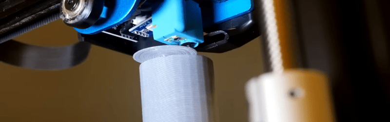
An accidental discovery by [3DQue] allows overhangs on FDM printers that seem impossible at first glance. The key is to build the overhang area with concentric arcs. It also helps to print at a cool temperature with plenty of fan and a slow print speed. In addition to the video from [3DQue], there’s also a video from [CNC Kitchen] below that covers the technique.
If you want a quick overview, you might want to start with the [CNC Kitchen] video first. The basic idea is that you build surfaces “in the air” by making small arcs that overlap and get further and further away from the main body of the part. Because the arcs overlap, they support the next arc. The results are spectacular. There’s a third video below that shows some recent updates to the tool.
We’ve seen a similar technique handcrafted with fullcontrol.xyz, but this is a Python script that semi-automatically generates the necessary arcs that overlap. We admit the surface looks a little odd but depending on why you need to print overhangs, this might be just the ticket. There can also be a bit of warping if features are on top of the overhang.
You don’t need any special hardware other than good cooling. Like [CNC Kitchen], we hope this gets picked up by mainstream slicers. It probably will never be a default setting, but it would be a nice option for parts that can benefit from the technique. Since the code is on GitHub, maybe people familiar with the mainstream slicers will jump in and help make the algorithm more widely available and automatic.
What will you build with this tool? If you don’t like arcs, check out conical slicing or non-planar slicing instead.


Well done my man! I have noticed this anomaly myself whilst printing when I accidentally bumped the machine and skewed the print destination Ive had wild overhangs that shouldnt have worked but did. As far as exploiting this you have done a great job thanks!
I’ll chip in a little that probably already suggested by others.
On the issue of warping, we probably could use conventional support method. These supports would ideally be placed at corners of the overhangs where cooling contractions would pull in. The support should be a cone shape with the tip intersecting into the overhang so to have enough material bonding, but not too much to make removal difficult. Bottom of the cone we could add conventional brim to increase bed adhesion. This would work well for outside overhangs, but I’m not sure with inside overhangs. It doesn’t have to be automated by the slicer, just have to provide cone style supports.
On second thought, pyramid style support might work too if arc moves of cone style is too expensive.
I think it might be possible to use the exact same technique by leveraging the concentric infill algorythm and running it with overlap and “in reverse”, from the center to the edge. functionally it should be the same, but might allow a cleaner fill pattern, at least on overhangs without concave perimeters. For concave perimeter overhangs the fill pattern would need to be split to make all sections convex.
Yeah, i beleive “arc” is not really important here. it might to eliminate sharp corners a bit and progressively get them sharper as geting closer to the outer shell, so the part looks sharper on the outside. But other than that i think there are much better ways to fill shape. you can take a look at the cnc mill pocketing strategies, they’ve been working on very similar problem for decades… Eg. “Adaptive pocket milling”.
Are arcs better than doing the same with lines/perimeters? Has anyone checked?
I haven’t tried. But I would expect so. If you do 90 degree corners, you always have a “disconnected” bit in the corner that wants to go down, while with arcs it is fully connected.
A small bit disconnected might not sound important, but the sagging down will compound and thus will get worse with each perimeter.
Still, with the right material and the right amount of cooling and the right amount of extrusion speed, you can extrude horizontal in the air. It’s just not very fast, and hard to tune.
My understanding here is that this type of curved paths (created by algorithm) are better because the nozzle while in motion is pulling melted filament onto already solidified part sideways, making it adhere better and with less sagging. In 3D printing conventional objects (with stacked layers) adhesion of melted plastic is provided by pressure of filament coming out of nozzle (melted plastic pressed vertically onto solidified structure) plus gravitational force (probably negligible as we’ve seen it’s possible to print FDM upside down).
So this curvature of path might provide additional pressure along horizontal plane helping to stick plastic together. It could be understood analogically to horizontally positioned nozzle (or printing overhangs with 5DoF printer).
If my theory is right, straight lines should be worse than arcs, but arcs might not be optimal paths.
But I might be wrong.
don’t know if i’m looking forward to trying to dial this in with my printer when the slicers start to support this out of the box. it might make it worthwhile to add the second fan to my end effector.
but to achieve a limited version of the same effect, but with traditional slicers…i’m sure others have discovered this same hack. but i just castellate the bottom layer of an overhang in openscad. by default the slicer will tend to make a long run parallel to the ledge, which doesn’t stand a chance…so this forces it to make a bunch of lines orthogonal to the ledge. i can’t go nearly as far out as in this demo! but it has been enough for my purposes. if you stack castellated edges, it makes angles close to 80 degrees plausible.
I had not heard of the castellation idea, so thanks for sharing.
I’m intrigued, could you share pictures of your approach?