[Learnelectronics] purchased some near-field EMI probes for his tiny spectrum analyzer for about $5 on sale. Could they be any good at that price? Watch the video below and find out.
The probes arrived as a kit with four probes: three circular ones for sensing the H field and a stubby probe for sensing E fields (although the video gets this backward, by the way). There’s not much to them, but for the price, it probably isn’t worth making them yourself if your concern is the cost. Now, if you just want to make your own, we get that, too, but don’t expect to save much money.
If you want an idea of what you can do with these probes, GW Instek has an application note titled “The Brand New Concept of EMI Probes” that, of course, uses their probes. You have to log in to view the document, but if you are handy with Google, you should be able to find a distributor with a copy of it in the open. Or, check out this article by Tektronix. You might also enjoy section 3.3.1 of Rohde and Schwarz’s white paper on the topic.
We’d really like to see these cheap probes compared to some of the higher-priced alternatives. There are also other designs we’ve seen. Whatever you are using, you ought to watch the 2020 Hackaday Remoticon workshop on debugging RF if you are interested in these probes.


> The probes arrived as a kit with four problems
Did you mean to say “problems”?
No, he meant to say “problems”. Wait, I meant “problems”. Wait, I meant “problems”. Wait, I meant “problems”…
I got 99 probes and EM probes ain’t one
Four probelems :D
don’t write problem instead, write em probe
I had not realized these were available from “china direct”.
Near field probes used to be in the category “specialized test gear” and cost several hundreds of Euro’s for a set, which is simply out of reach for a lot of students and hobbyists. A few years ago Dave from the EEVblog made some video’s about near field probes (including some self made from semi ridgid coax) and it was an eye opener to see how simple these things are.
These things also do not need to be very accurate, Making them accurate would be very difficult because the distance to what you’re measuring has a huge influence. They also do not need to be accurate for localizing EMC problems and getting some general ballpark numbers of EMC compliance.
I’m not entirely sure, but I think it’s a bad thing that it picks up the local radio station (@03:09) so clearly. From what I remember from Dave’s old video he bent the semi ridgid coax in a loop so it was used as shielding for the electrical field, and it only picked up the magnetic field.
I’m wondering if there are doable DIY methods for getting some reasonable idea of the frequency response and flatness of these things.
Stick one of these probes in place of the hotend on your 3d printer, put the pcb on the bed, and map out the EMI as a point cloud. Then you have the distance you’re measuring as accurate as, well, you can measure. I’ve done this to localize loud emissions and it’s pretty easy. We set it up so that it would go to each point in our 3d test area and pause for two seconds, while we manually triggered a reading, but doing full automation seems like it should be pretty easy. We just couldn’t get a decent serial connection independent of a printer control program, eg using minicom or putty.
That is of course easy enough, but it’s still an un-calibrated relative measurement. It’s fine for finding the strongest emission points, but it does not help for absolute field strength. This would need some kind of known field strength, maybe with a Helmholtz coil?
> Watch the video below and find out.
Listen, it’s nice to want to drive traffic towards these kinds of channels, and I understand the want to support people. But the reason I’m on hackaday instead of just letting youtube recommend stuff to me is less because of the curation and more because I don’t want to spend the time watching a bunch of videos.
Provide usable synopsis please, feel free to try to drive traffic to the channel by talking about other stuff they do but this isn’t the first video that was summarized as “watch the video”.
I have to agree. This isn’t a movie that I don’t want spoiled, it’s a 10 minute video that can be summarized in a few lines. Even just saying “he found they were pretty good in application A and B, but not so much in C because of D” is going to go a long way to help me determine if I want to invest in the video.
I agree with this comment! Will likely visit the site later to check out the video, but only if I have an idea of what I will be getting in return for my time.
“don’t want to spend the time watching a bunch of videos.”
++++1
I never liked the exposed microstripline on these cheap ones, it tends to capacitively couple into my hand. I ended up designing some of my own a couple years ago using stripline on a 4-layer board.
https://github.com/JeremyRuhland/OpenFieldProbe
Those look pretty nice. Any chance you can generate the gerbers or somehow export to Kicad?
The difference between the good probes and the cheap ones is the common mode rejection. The best are made by Langer EMV. They are precise and calibrated. At the other end a coax with the center cable soldered to the shield also works. Be careful not to short stuff with the exposed wires and keep in in the cheap one will measure both CM and DM, which is generally undesirable.
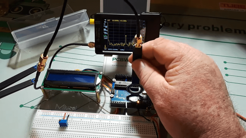
OK here it is, video synopses: He tries the probes on an arduino with his TinyVNA and all but the tiny probe gave a clear peak on 16MHz which is the crystal frequency of the arduino.
So in short they work fine.
The tiny one is meant for very high frequencies I would think.
The first, largest one, he tried also showed a small peak for the local radio station.
The end. Now is it so bad that he gets a few views for s short video?
Addendum: He should of course also have tried some side frequencies that might be produced by certain scripts on the arduino pins, to see if they would differentiate in the plot, but he did not and you’ll have to spend the 6 bucks to try it yourself. Assuming you have something to use the probes with, but you’d not care either way otherwise.