We’ve seen a number of people create plasma speakers over the years here at Hackaday, so at first blush, the latest Plasma Channel video from [Jay Bowles] might seem like more of the same. Even his overview of the assembly of the 555 timer circuit at the heart of the setup, as detailed as it may be, is something we’ve seen before.
But the back half of the video, where [Jay] talks about the flyback transformer used in this plasma speaker, really got our attention. You see, frustrated by the limited options on the market for AC flybacks, he set out to put together a custom transformer utilizing a 3D printed secondary former of his own design.

Armed with a spare core, [Jay] spent some time in CAD coming up with his secondary. Despite never having built a flyback before, his first attempt managed to produce some impressive sparks — that is, until it arced through the printed plastic and released the critical Magic Smoke. Inspired by this early success, he went back to the digital drawing board and cranked his way through several different iterations until he came up with one that didn’t self-destruct.
Once he had a coil that was working reliably, he hooked it up to his Bluetooth-augmented 555 circuit, and started playing some tunes from his phone. While it might not be our ideal way to listen to the latest episode of the Hackaday Podcast, we’ve got to admit that the audio quality was fairly impressive. Music coming through the air with no visible speaker element has an almost magical quality to it — this is definitely the sort of thing that would have gotten you burned at the stake back in the day.
Despite his troubles with the printed component, a look at the final result is a reminder of how simple a flyback transofmer really is when you get right down to it. A few windings of thick wire on one side of the core, a whole lot of windings of thin wire on the other side, and you’re good to go. Of course, a printed jig like this certainly makes for a neater final product, especially if you end up encapsulating the whole thing in epoxy.
Not interested in winding your own coil? [Jay] has put together an instructional video on building a high-voltage supply with the sort of commercially available flyback you’d find in a CRT. If it’s the singing plasma that’s got you interested, you might want to take a look at one of his earlier projects that was based on Honda ignition coils.


Okay, question for the more knowledgeable people here.
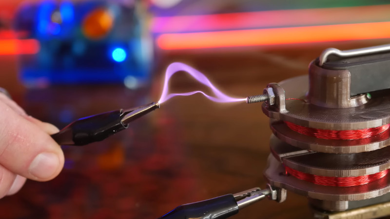
At the start of the video he holds an alligator clip/wire in his hand to the output to get a spark.
The insulation of jumper wires with alligator clips is rated at 700 volts, right?
It seems like holding an alligator clip like that in your hand is really bad practice, it’s probably OK for the little circuit he has, but it’s good practice to practice good practice on the little/safe circuits so that it becomes a habit when you’re working with more dangerous circuits.
Not being a safety nanny here, but not being a nanny is recognizing the dangers and practicing good technique to avoid the dangers, so…
Does this seem like bad practice to anyone else?
(I work with a 13 MHz RF generator that will output 700 watts and will electrify everything piece of metal in the room, including wire-rimmed glasses, if given half a chance. Chicken sticks are your friends.)
Sputtering power supply? Size and frequency are familiar.
As long as that alligator clip doesn’t come unclipped from ground, it’ll be fine. And I don’t know that that circuit could be lethal in worst case. All down to Jay’s risk tolerance.
The alligator clip closes the circuit of the transformer, and most likely it’s also grounded. That\s why he doesn’t get shocked. If he tried this with the other wire, he might have gotten a nasty burn and some residual effects, especially with his heart. That’s why it’s important to go to a doctor after receiving an electric shock.
Isn’t the whole point that the alligator clip and thus to other end of the coil is not grounded so that the arc has no desire to go through Jay to ground?
Not really. The path between the ends is the least resistance. If the one end of secondary is grounded, the path through Jay to ground has higher impedance. At those frequencies skin and cable insulation act more like dielectric in capacitor than pure resistive insulation. There will be some leakage current anyway, as Jay is a capacitor to ground via air, but this flow is too small to cause any damage.
Some people made Tesla Coils where one end is not grounded and load capacitances (toroids) are on both end of the secondary coil. The danger of this setup is that either end can find a path to the ground through a human who isn’t careful. Once you become the best path to ground, you’re screwed, unless you know, what you’re doing. The whole thing is quite complex set of relationships we can’t really test without human sacrifice, which currently is a big no-no.
Watch this video:
https://www.youtube.com/watch?v=BGD-oSwJv3E
There is no evidence that one end of the secondary is grounded.
Ah! I did something similar just last year using a resin 3D printer and a spare flyback core to power an old RADAR CRT. https://imgur.com/a/Ihrijd5