Harvesting Namib Desert Fog With High Voltage

As fun as mucking about with simulated environments in a laboratory is, at some point you have to do those field tests to demonstrate that your prototype actually works in the real world, under real conditions. This is what the [Plasma Channel] recently did for their fog harvesting system by setting it up in the Namib desert.

We previously covered the atmospheric water harvesting attempts, using electrostatic precipitation to draw the moisture in the air onto the collectors where it can then be harvested. This is rather different from existing approaches with e.g. fine meshes and hoping that enough water molecules bump into your mesh, so theoretically it should be much more efficient. In the lab it worked well, but reality always has the last word.

The Namib desert is at the top of the world’s most arid regions, competing with the Atacama desert. What it does have going for it is regular fog rolling in that lasts until sunrise, providing a good target for water harvesting. Interestingly, this field test was performed together with the University of Namibia.

Of course, moving the prototype in check-in luggage for the flight to Namibia took some redesigning and testing. Fortunately everything, including the solar panel, arrived intact, allowing trials to commence. This initially took place at the campus of the University of Namibia, joining a number of other atmospheric water harvesting projects that had been previously installed there.

Unfortunately the fog proved to be rather elusive, leading to a few fruitless attempts. It also proved that the salt in the air from the ocean spray, even a few kilometers inland, was highly corrosive, especially to high-voltage electronics. Although the system basically worked, happily harvesting water under the right conditions, it does need some redesign before it’ll be tested next in the Atacama desert.

Continue reading “Harvesting Namib Desert Fog With High Voltage”
Blow Those Pyros With A Telephone!

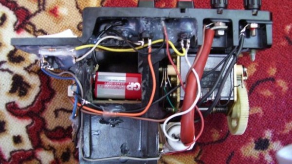
A pyrotechnic charge is set off by passing a high voltage through a filament within it, melting the filament and igniting the charge. We could think of a variety of circuits that could do this, but perhaps we wouldn’t have come up with [Michał Słomkowski]’s solution. He’s used the ringer crank generator from an old military field telephone. It’s an old project he’s shared with us due to its recent republishing on his website.

The basic principle is simple enough, winding the generator charges a capacitor bank through a bridge rectifier. Then a thyristor is used as the trigger device, dumping the contents of the capacitor into the filament. But the full circuit has a couple of refinements. There’s a charge indicator circuit using a couple of Zener diodes and an LED, and a filament tester which passes a non-triggering current through the filament from a 9 volt battery. We like the use of an over-the-top high-current thyristor, no doubt what he had in his junk box.

Perhaps it’s a symbol of how far technology has moved, that today it’s surprisingly rare to find a bridge rectifier or a thyristor, and building this device today would involve a microcontroller and probably an AliExpress inverter module as a matter of course.

Meanwhile, should field telephones interest you, we’ve been there before.

Old TV Vacuum Tube Turned DIY X-Ray Machine

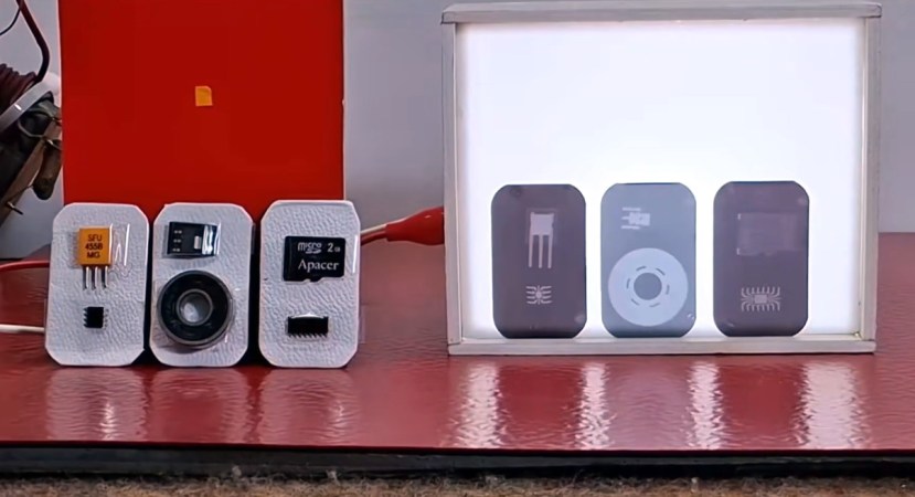
Just because you probably shouldn’t make a DIY X-ray machine, doesn’t mean nobody would. [mircemk] shows off his DIY unit, how it works, how to use it safely and of course, some pretty X-ray photos of household objects.

The machine repurposes a DY86 vacuum tube from old CRT TVs to emit X-ray radiation. To drive the tube without blowing it up, a rather specialized series of power supplies is needed; a low-voltage DC power supply powers a high-voltage AC inverter, which is then sent through first a transformer, and then a Crockfort-Walton voltage multiplier, to reach the incredibly high voltages needed for such a vacuum tube’s radiation emission to reach X-rays. Naturally, this didn’t go to plan first try, leading to the unfortunate demise of three vacuum tubes (as well as another three which had already lost their vacuums).

Now how do you capture an image with X-rays for a light source? With dental X-ray photo films of course! The dental film is placed behind the object to be scanned, the transmitted X-rays making up the resulting image. After going through the standard process of developing for about 30s, washing, fixing for about half an hour, and washing again, the photos become clearly visible. The best results were obtained at a distance of 10-15 cm an an exposure time varying from 15 minutes to an hour depending on material hardness.

Continue reading “Old TV Vacuum Tube Turned DIY X-Ray Machine”

How To Bias A CRT After Installation

For most of us the abbreviation “CRT” brings to mind a monitor or TV. But at its core it’s about the special vacuum tube that makes the images appear.

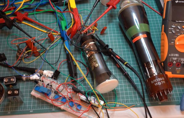
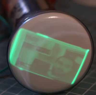
Regardless of whether it’s just a simple monochrome CRT in an oscilloscope or a full RGB CRT, the basic steps to make it work in a device remain the same. In a recent video by [Void Electronics] these steps are worked through, including the biasing at the end that is necessary to get a stable image.

A big part of installing a CRT and driving it is knowing how to read its datasheet. Much like other vacuum tube types, there are heaters, control grids and a range of voltages to get right and keep happy. Even then you can still have a situation where you must troubleshoot problems, which is also touched upon in the video. All of this is demonstrated using an RFT B6S1 CRT as the subject, including how to build your own bias circuit.

Despite calling it an “obsolete skill”, there is still a lot of demand for CRTs in vintage lab equipment, arcade restorations and far more obscure fields that still have new CRTs produced for them. Not to mention that even today CRTs have characteristics that make them competitive with flat-screen technologies.

Continue reading “How To Bias A CRT After Installation”

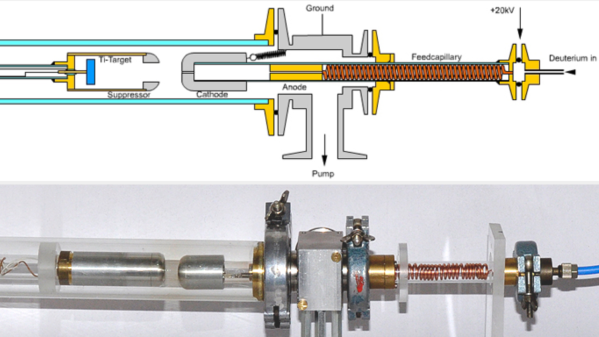
A diagram of a neutron generator is shown in the top portion of the image, with the physical version below.

A Benchtop Neutron Generator For The Home Reactor

There are a surprising number of experiments an amateur nuclear physicist can perform, from making a Geiger counter to fusing hydrogen atoms in a fusor. One project which we haven’t seen before is a neutron generator, such as the benchtop neutron generator made by [Rapp Instruments] (translated).

This particular generator takes a feedstock of pure deuterium, which it ionizes and accelerates into a titanium target. The first deuterium nuclei to hit the target react with it to form titanium deuteride, immobilizing them until more ions strike them and they undergo nuclear fusion. The fusion reaction mostly forms helium-4, but sometimes forms helium-3 and a free neutron, which is radiated away. The radiated neutrons are slowed down by a block of high-density polyethylene, and a portion of them strike a silver or indium foil wrapped around a Geiger counter tube. The neutrons activate the silver or indium, and the Geiger counter detects the resultant increase in radioactivity.

The design is a linear particle accelerator built inside an evacuated glass tube. It uses two high-voltage power supplies: a 20 kV supply which ionizes the deuterium gas fed into the tube, and a 100 kV supply which accelerates ions emitted from the source into the target. The target itself is surrounded by a cup-shaped electrode to capture secondary electrons emitted during impact. To prevent arcing, the tube needs to be at a very low pressure, reached by extensive use of an oil diffusion pump.

Radioactivity measurements of the silver and indium foils showed that the generator did work; when irradiating the silver foil for five minutes, it generated 175 counts per second after the neutron source was turned off. Plotting the count rate versus time suggested that a mixture of two silver isotopes was being generated, Ag-110 and Ag-108, based on their half-lives. Irradiation of indium produced a similar exponential decay in radiation.

We recommend checking out the rest of the site; it’s a gold mine of projects, such as this mass spectrometer. For more background on neutron generators, we’ve covered their theory and some of the more common varieties.

Passive Bug Zapper Tracks Its Kill Count

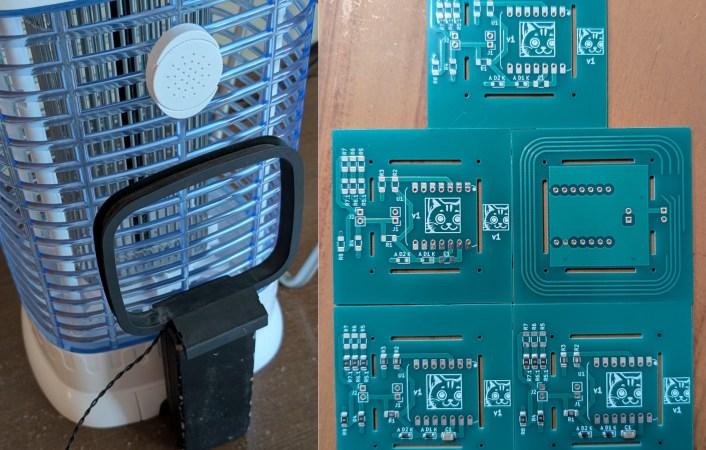
If it’s summer in a warm, humid climate, bugs can be the bane of your existence. A natural solution is to place a passive bug zapper to catch bugs at night. But what if that isn’t fancy enough? [Nicolas Boichat] spices it up with a passive bug zapper that tracks its kill count.

But how exactly do you detect a bug zap? With an antenna, of course! When a bug gets caught, it arcs, creating an electromagnetic pulse. A small loop antenna on the backside of the zapper receives the signal.
Continue reading “Passive Bug Zapper Tracks Its Kill Count”

A Simple Switch For Simply Too Much Current

A switch is simple: connect two pieces of metal together and bam! Except, it’s not that simple at high currents. How much current? Just about 400 car batteries worth would certainly cause some issues. This is the issue that [Technology Hobby] hoped to fix with his clever switch design.

While many content creators are great at finding or making high-current sources (looking at you, Styropyro), their switches can’t always hold up to the abuse. [Technology Hobby] found that many of the switches used by these creators had issues based on an inconsistent and limited contact area. Making a bigger contact patch is always fairly easy; keeping those contacts from skipping can be a bit more difficult.

Continue reading “A Simple Switch For Simply Too Much Current”