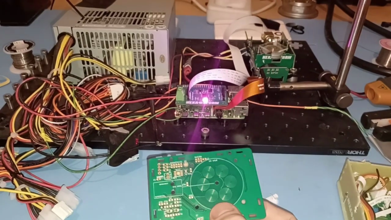
[Rik]’s Hexastorm laser scanner project originally used a discrete polygon mirror controller+motor module from Sharp to spin a prism. But the scanner head was a bit difficult to assemble and had a lot of messy wires. This has all been replaced by a single board featuring a PCB-printed motor, based on the work of [Carl Bugeja]. The results are promising so far — see video below the break.
Since the prism is not attached to anything, currently it will fall off if mounted in the intended vertical orientation. One of [Rik]’s next steps is to improve the mount’s design to constrain the spinning prism. The previous Sharp motor was specified to 21000 RPM, but was only driven to 2400 RPM in [Rik]’s first version. This new PCB motor spins at 2000 RPM in these tests, comparable to his previous experiments ( we’re not sure about the maximum RPM ).
See our original writeup from 2019 to review the goals of this project, and be sure to checkout details and documentation on the Hexastorm project page. To learn more about PCB motors, read our article about [Carl]’s first design and visit his Hackaday.io page. Thanks to [Jonathan Beri] for the tip.


This would be beautiful if it had double-sided eurocard (160 x 100) exposure abilities, automatic board & image registration when flipped, and a gui allowing gerbers to be lased. Dreams.
Maybe i misunderstand something, but how is 4-5 wires in a ready-made scanner module with great bearings and motor “a lot of messy wires”? It’s OK to make your own, but this this feels like reinventing the wheel? Also, this assembly is missing the f-Theta lens that is needed to focus the laser onto a flat surface i believe.
Hey Zapro,
Thanks for your reply.
The old motor needs 5 wires and 4 screws. In addition, the mirror is removed and a prism is placed on top.
The idea here is to further compact and “own” the technology. For a single scanner the benefits are not
high. If you are building thousands or making a laser scanner with 288 bundles like Kleo LDI. I believe the
added benefit is high.
Typical, laser scanners use rotating mirrors. If you use a prism, a f-theta lens is not needed.
This reduces costs as well and has some added benefits; orthogonal projection and lower cross scan
error.
I’m assuming the point is to aim the laser beam in two dimensions onto an arbitrary point on a flat surface. I cannot see how the rotating prism accomplishes this. None of the easily searchable references are very illuminating.
I have the same question. All of the examples show two-dimensional result but there is no explanation as to how that can be achieved with a single rotating prism.
I’m sure [Rik] can chime in with a better explanation, but in the original version this scanning head was mounted on a carriage that stepped the whole thing up and down (left and right?), thus giving 2D coverage.
Correct Chris, to produce the PCB, I mounted the laser head on a robot arm and moved in the other direction.
see https://youtu.be/dR09Tev0cPk . This is similar to how it is in done in the Formlabs 3.
In imaging applications, a combination of two prisms is used see https://hackaday.io/project/21933/log/167047-sx10-wide-scan-angles-with-prisms
Looking at this exploded view of a typical Sharp polygon mirror scanner motor from AliExpress, it looks like the PCB is somehow participating in the “motor”, but not in the same way as Carl’s PCB motor designs.
https://ae01.alicdn.com/kf/UT8YTiFXoxbXXagOFbXb/201098584/UT8YTiFXoxbXXagOFbXb.jpg
The PCB has an alluminum back end, I provide more details on the motor here https://hackaday.io/project/21933-prism-laser-scanner/log/199831-bldc-motor
Any reason an RC outrunner mirror can’t be used?