PCB Motor Holds Fast, Even After 1.6 Billion Spins

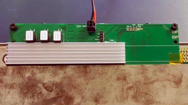
If you aren’t up to date with [Carl Bugeja]’s work with tiny brushless PCB motors, his summary video of his latest design and all the challenges it involved is an excellent overview.

Back in 2018 we saw [Carl]’s earliest versions making their first spins and it was clear he was onto something. Since then they have only improved, but improvement takes both effort and money. Not only does everything seemingly matter at such a small scale, but not every problem is even obvious in the first place. Luckily, [Carl] has both the determination and knowledge to refine things.

Hardware development is expensive, especially when less than a tenth of a millimeter separates a critical component from the junk pile.

The end result of all the work is evident in his most recent test bed: an array of twenty test motors all running continuously at a constant speed of about 37,000 RPM. After a month of this, [Carl] disassembled and inspected each unit. Each motor made over 53 million rotations per day, closing out the month at over 1.6 billion spins. Finding no sign of internal scratches or other damage, [Carl] is pretty happy with the results.

These motors are very capable but are also limited to low torque due to their design, so a big part of things is [Carl] exploring and testing different possible applications. A few fun ones include a wrist-mounted disc launcher modeled after a Spider-Man web shooter, the motive force for some kinetic art, a vibration motor, and more. [Carl] encourages anyone interested to test out application ideas of their own. Even powering a micro drone is on the table, but will require either pushing more current or more voltage, both of which [Carl] plans to explore next.

Getting any ideas? [Carl] offers the MotorCell for sale to help recover R&D costs but of course the design is also open source. The GitHub repository contains code and design details, so go ahead and make them yourself. Or better yet, integrate one directly into your next PCB.

Got an idea for an application that would fit a motor like this? Don’t keep it to yourself, share in the comments.

Continue reading “PCB Motor Holds Fast, Even After 1.6 Billion Spins”

High Caliber Engineering On A Low Torque PCB Servo Motor

Building a 3D motor printed motor is one thing, but creating a completely custom servo motor with encoder requires some significant engineering. In the video after the break [365 Robots] takes us through the build process of a closed-loop motor with a custom optical encoder.

The motor, an axial flux design, uses a stack of 0.2mm PCBs with wedge shaped coils clamped in a 3D printed body. It’s similar to some of the other PCB motors we’ve featured, but what really sets this build apart is its custom optical encoder, which was a project in its own right. The 4-bit absolute position encoder uses IR LEDs to shine through an PCB disc with concentric gray code copper encoder rings onto IR receivers. This works because FR4, the composite material used in PCBs doesn’t block IR light.

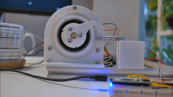
The motor’s body was printed from ABS to withstand the heat during operation. [365 Robots] didn’t skimp on the testing either, creating a 3D printed closed-loop test stand with load cell and Arduino. Like other PCB motors it produces very little torque, roughly 2% of a typical NEMA17 stepper motor. Even so, the engineering behind this project remains impressive.

Continue reading “High Caliber Engineering On A Low Torque PCB Servo Motor”

What Makes Wedge Coils Better Than Round For PCB Motors?

PCB motors are useful things. With coils printed right on the board, you don’t need to worry about fussy winding jobs, and it’s possible to make very compact, self contained motors. [atomic14] has been doing some work in this area, and decided to explore why wedge coils perform better than round coils in PCB motor designs.

[atomic14]’s designs use four-layer PCBs which allow for more magnetic strength out of the coils made with traces. While they’ve tried a variety of designs, like most in this area, they used wedge-shaped coils to get the most torque out of their motors. As the video explains, the wedge layout allows a much greater packing efficiency, allowing the construction of coils with more turns in the same space. However, diving deeper, [atomic14] also uses Python code to simulate the field generated by the different-shaped coils. Most notably, it shows that the wedge design provides a significant increase in field strength in the relevant direction to make torque, which scales positively on motors with higher numbers of coils.

This kind of simulation and optimization is typical in industry. It’s great to see an explainer on real engineering methods on YouTube for everyone to enjoy. Video after the break.

Continue reading “What Makes Wedge Coils Better Than Round For PCB Motors?”

Single Flex PCB Folds Into A Four-Wheel Rover, Complete With Motors

You’ve got to hand it to [Carl Bugeja] — he comes up with some of the most interesting electromechanical designs we’ve seen. His latest project is right up there, too: a single PCB that folds up into a four-wheel motorized rover.

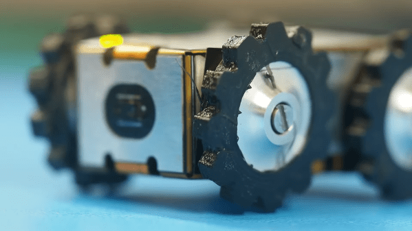
The key to [Carl]’s design lies with his PCB brushless motors, which he has been refining since we first spotted them back in 2018. The idea is to use traces on the PCB for the stator coils to drive a 3D printed rotor containing tiny magnets. They work surprisingly well, even if they don’t generate a huge amount of torque. [Carl]’s flexible PCB design, which incorporates metal stiffeners, is a bit like an unfolded cardboard box, with two pairs of motor coils on each of the side panels. This leaves the other surfaces available for all the electronics, with includes a PIC, a driver chip, and a Hall sensor for each motor, an IMU and proximity sensor for navigation, and an ESP32 to run the show.

With machined aluminum rotors and TPU tires mounted to the folded-up chassis, it was off to the races, albeit slowly. The lack of torque from the motors and the light weight of the rover, along with some unwanted friction due to ill-fitting joints, added up to slow progress, especially on anything other than a dead flat surface. But with some tweaking, [Carl] was able to get the buggy working well enough to call this one a win. Check out the build and testing in the video below.

Knowing [Carl], this isn’t the last we’ll see of the foldable rover. After all, he stuck with his two-wheel PCB motor design and eventually got that running pretty well. We’ll be keeping an eye out for progress on this one.

Continue reading “Single Flex PCB Folds Into A Four-Wheel Rover, Complete With Motors”

Laser Scanner Upgraded To Use PCB Motor

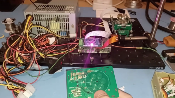
[Rik]’s Hexastorm laser scanner project originally used a discrete polygon mirror controller+motor module from Sharp to spin a prism. But the scanner head was a bit difficult to assemble and had a lot of messy wires. This has all been replaced by a single board featuring a PCB-printed motor, based on the work of [Carl Bugeja]. The results are promising so far — see video below the break.

Since the prism is not attached to anything, currently it will fall off if mounted in the intended vertical orientation. One of [Rik]’s next steps is to improve the mount’s design to constrain the spinning prism. The previous Sharp motor was specified to 21000 RPM, but was only driven to 2400 RPM in [Rik]’s first version. This new PCB motor spins at 2000 RPM in these tests, comparable to his previous experiments ( we’re not sure about the maximum RPM ).

See our original writeup from 2019 to review the goals of this project, and be sure to checkout details and documentation on the Hexastorm project page. To learn more about PCB motors, read our article about [Carl]’s first design and visit his Hackaday.io page. Thanks to [Jonathan Beri] for the tip.

Continue reading “Laser Scanner Upgraded To Use PCB Motor”

Exploring The Hall Effect For Haptic Feedback PS4 Joysticks

Modern gaming console controllers aren’t without their annoyances — Joy-Con drift, anyone? The problems might stem from design deficiencies, but we suspect that user enthusiasm and the mechanical stress it can introduce might play a significant role as well. Either way, [Marius Heier] decided to take a look at what would be required to build a better joystick and came up with some interesting results.

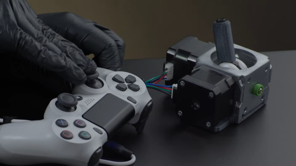
The first video below lays the basic groundwork, with a bunch of experiments with 3-axis Hall effect sensors, specifically the Texas Instruments TMAG5273 and TMAG5170. They’re essentially the same sensor with different interfaces — SPI for the 5170 and I2C for the 5273. Using just one of these sensors, he was able to build a joystick with the usual X- and Y- axis control, but also with a rotary axis. What’s more, he built a motorized version using two NEMA 17 steppers to mechanically drive the stick back to center.

The joystick is bulky, but it looks like he’s got plans for a much smaller one with [Carl Bugeja]-style PCB motors that should fit into a PS4 controller. That’s the subject of the second video below, which uses a different Hall sensor — an Allegro A1304 — and is mainly concerned with getting the output of a non-motorized but considerably miniaturized joystick stick talking the language that the controller expects. It’s not a simple process, but it seems to be coming along nicely, and we’ll be watching progress closely.

Continue reading “Exploring The Hall Effect For Haptic Feedback PS4 Joysticks”

A Fast Linear Actuator Entirely In One PCB

There are many ways to make a linear actuator, a device for moving something is a straight line. Most of the easier to make ones use a conventional motor and a mechanical linkage such as a rack and pinion or a lead screw, but [Ben Wang] has gone for something far more elegant. His linear actuator uses a linear motor, a linear array of coils for the motor phases, working against a line of magnets. Even better than that, he’s managed to make the whole motor out of a single PCB. And it’s fast!

This represents something of an engineering challenge, because achieving the required magnetic field from the relatively few turns possible on a PCB is no easy task. He’s done it by using a four-layer board to gather enough turns for the required magnetic field, and a simple view of the board doesn’t quite convey what lies beneath.

PCB motors are perhaps one of those areas where the state of the art is still evolving, and the exciting part is that their limits are being pushed right there in our community. And this isn’t the only linear motor we’ve seen recently either, here’s one used in a model train.