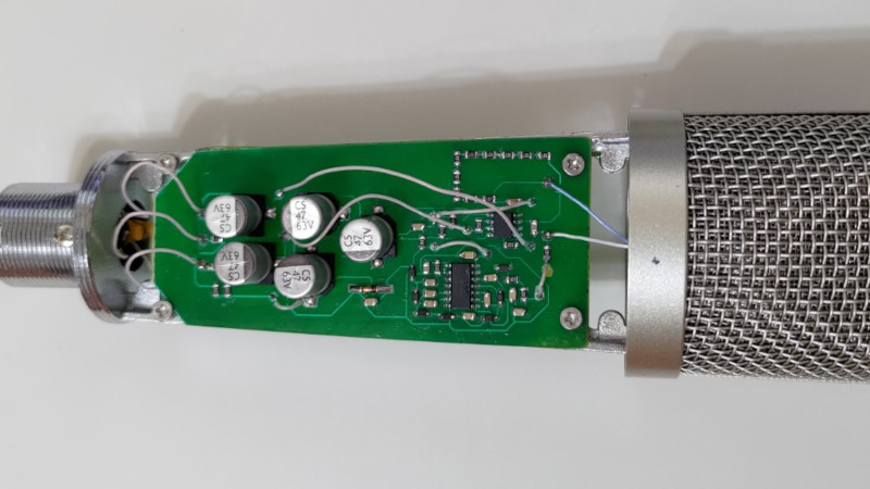
As the Internet has turned so many of us into content creators, we’ve seen the quality of webcams and microphones steadily increase to the point at which even a fairly modestly-equipped YouTuber now captures their wisdom at a quality far exceeding that you might have found in some broadcast studios not so long ago. Still, decent quality costs money, and for that reason [Spirit532] has built his own high quality condenser microphone for less expenditure.
 The capsule and body are off-the-shelf items — what he’s produced is the bias voltage supply and preamplifier. In both cases these are the interesting parts of a condenser microphone, so their circuit bears a second look.
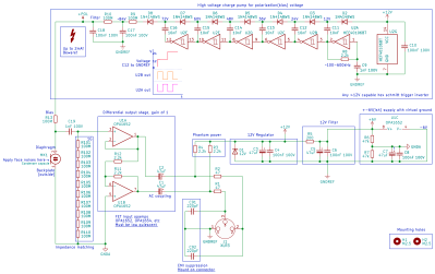
The condenser microphone takes a diaphragm and turns it into one side of a capacitor. If you apply a charge to this capacitor, the voltage over it changes minutely with the capacitance as the diaphragm vibrates. Thus to have a usable audio signal level a high-voltage bias supply is required to provide the charge, and a very high impedance preamplifier circuit to catch the signal without draining the capacitor.
His bias supply is a charge pump using a string of diodes and capacitors fed by a chain of CMOS inverters, with an RC filter and resistor chain to provide that super-high impedance. The preamplifier meanwhile is a unity gain high-impedance op-amp with an inverting stage to provide a balanced connection. For good measure the circuit also includes a phantom power supply.
This is an interesting project for anyone with an interest in audio. if you’re further interested in condenser microphones, how about also looking at electret microphones?


Hey, author here. Small correction: the circuit *uses* phantom power, it doesn’t just tack it on there “for good measure”, the circuit is fed via 48V phantom provided by the audio interface :)
Thanks for clarifying I was gonna hit the comments to ask because it wasn’t clear. Good job by the way.
Am I the confused circuitist here, or is “1 GΩ differential impedance matching” strange?
The used opamps have differential input impedances about 1/10 of that, so that this even theoretically has basically no effect at all. Also: if your desired large resistance isn’t available in an SMD package, that’s probably because you can’t isolate the contacts enough over that distance. Putting multiple of these resistors in series then makes a lot of sense. However, not separating the traces on the board by at least the series resistance dimensions … Hm.
What’s the point of impedance matching here, as well? This isn’t RF, the traces are much shorter than electrical wavelengths, we’re not aiming for maximum power transfer, right?
Is that “12V regulator” kind of industry standard?
That’s a sole Zener diode shunt with high-ohmic input at a reverse bias, so you’re getting Zener effect-caused noise. This looks surprising much like a classical circuit called *shot noise generator*. Luckily, there’s large capacitor stages to filter that wideband noise afterwards; so the noise gets high-pass filtered, with a cutoff at around 50 Hz. Is that enough to keep GNDA clean enough? Any noise on GNDA is directly differential input noise to the differential amplifier.
I found that without the 1GΩ on the input, something(not quite sure what) tended to charge up and result in the circuit going deaf(~30dB signal drop). I haven’t simulated it at all, but it’s what happens. When putting the capsule itself across 1GΩ, it’d just charge up the diaphragm and stick itself to the plate, resulting in the same.
By “impedance matching” I just meant the overall impedance of the capsule(hundreds of GΩ) to the impedance of the input line(usually around 3.8k in mic mode for most interfaces), not RF or anything of the sort.
A shot noise generator would have a resistor in series with the Zener, not before it, and the barrier is used to generate noise. This is just a regular Zener regulator. Similar, and I get where the confusion comes from, but all the shot noise just goes to ground here(including through the filter, since it’s a very fast transition).
GNDA is clean enough to not affect the audio performance in any significant way. The mic can hear about 4dB better than I can myself, and I can catch conversations happening under my window that I can’t hear myself, with no electrical noise audible at max gain. Unfortunately that’s the only metric I have(no isolated scope, no calibrated audio measurement equipment), so it’ll have to do.
aaaaah! yeah that makes lots of sense! Thanks!
The input current of this Op Amp is ~10pA. Even if the leakage resistance of the series coupling cap is in hundreds of GΩ, it would be enough to slowly charge the input gates towards the Vcc and exceed the common-mode input voltage of the amplifier. The 1GΩ resistor drives these minuscule DC currents to ground nicely, while being large enough to prevent any meaningful low-end rolloff.
The input current often bites newbie designers who then wonder why their sample and hold circuit won’t hold…
Interesting project. I had a look at the schematic diagram and I have an issue with the balanced output.
The goal of a balanced output is to present identical output impedance at both the hot and cold output. There is no need to present a signal on both outputs, it works just as well with a single one, as long as the impedances on hot and cold output are matched.
In your schematic the cold output is taken form the hot output and inverted. This has poor common mode rejection. If noise is picked up on both hot and cold in the microphone lead (called common mode) you will notice the undesirable effect. Any incoming noise on the cold output will be countered by the negative feedback on the opamp driving the cold output. However part of the noise on the hot output will be fed to the opamp driving the cold output, effectively adding more noise instead of rejecting it.
One solution is to remove the opamp for the cold output and connect the circuit where its output would have been to agnd. Output impedances will still be identical, since the remaining opamp has a low output impedance which is no different from tying to gnd. This will monolithicimprove your common mode rejection, since there is no more noise added by the inverting trick. It will also be lower noise, since there is a single opamp now you have halved the noise contributed by the opamp.
If you have a need to drive both hot and cold output, look at monolithic differential output drivers. THAT Corp has some good ones. They even have instrumentation amplifiers with differential outputs, such as the THAT 1580, designed for application in microphone preamps. THAT corp also has excellent application notes on their products, explaining about CMMR and a lot more.
Alternatively, use an output transformer. It will make a perfectly balanced output without common mode problems. As a bonus, phantom power comes out the center tap of the transformer, saving you a couple of resistors and leaving a little more power to work with.
Good catch, the schematic does have a common mode rejection issue! But, from the final result I can say that either it’s not actually an issue, or I haven’t encountered enough induced common mode noise to make it one(and my lab is very noisy). Additionally, connecting the output to AGND isn’t actually possible, since it’s virtual ground derived from GNDREF.
The situation can be improved slightly by dropping the feedback resistor values or shorting them entirely to get an excellent* CMRR, but I haven’t tested how stable the opamps would be in that configuration(especially short).
Regarding your suggestion to use chips by THAT or transformers – this goes directly against the project’s idea of using cheap, readily available parts(the OPA1652 *can* be replaced with any dual jfet opamp, it just probably shouldn’t be). And transformers… yeah, no. Absolutely not. That can almost double the cost of the whole project.
*ish
It’s good to hear your microphone perform well in a noisy environment. It might be more of an academical problem than.
But let’s see what we can do without transformers, expensive ICs and virtual ground.
Well, if you use U1A for buffering the capsule output, you could use U1B for buffering AGND. Both hot and cold will be driven by identical source impedances, but without the earlier feedback problem.
Or, to keep things more symmetrical, something along this way:
https://www.analog.com/en/analog-dialogue/articles/differential-output-difference-amp-system.html
This is a very interesting remark. I would hope that the 47Ω series resistance (R2) will prevent the noise currents from affecting the voltage on Op-Amp pin #1 from which the inverted output is provided. This node should have extremely low AC impedance, getting worse however the higher we go in frequency. Why isn’t it the case?
“If you have a need to drive both hot and cold output, look at monolithic differential output drivers.”
Why not drive the non-inverting and inverting op amps in parallel?
I have seen circuits where 3 op amps are used – one as the gain stage, feeding the other two in parallel, one inverting and the other not. But this design is for unity gain, so maybe the first op amp isn’t needed?
Nice project. What’s the max frequency it can sense? 200 KHz would be nice.
Cool! This is very similar to my Instructable here: https://www.instructables.com/True-Condenser-OPA-Mics/ Although, why you didn’t go straight to a 1gig resistor is interesting.
I did take a peek at yours for inspiration! Mentioned it on GitHub too, just in case people find it too similar :)
If you mean why I didn’t use a single 1gig part, it’s due to accessibility and cost. 100M is a standard SMD value that can be sourced and placed everywhere for pennies, whereas 1gig is a little more painful to find, is often pricier, and even more often THT if you don’t want to blow the budget.
If you mean why I biased it with 100M(+filtering) and put the 1G after the cap, it’s to discharge the fet input gates, which also takes care of coupling cap leakage.
I was more speaking of putting 10 100M resistors in series. The problem is board cleanliness and humidity. I actually use a through hole for it on my mic boards. JLI Electronics carries them. It is great to see another take on this. And: No through hole fets or transformers. lol. I presented this at last AES and it was well received. The distortion is orders of magnitude better than the Schoeps circuit (one fet two PNP’s) from 50 years ago. It is still the most commonly used too!
Jules
Here’s an interesting video on the subject that has a good technique to eliminate one of those high-value resistors: https://www.youtube.com/watch?v=niZizzHBanA&list=PLvOlSehNtuHv98KUcud260yJBRQngBKiw&index=7
I’d also definitely bias the capsule through more than 100M, because that’s a low-pass filter on the signal with a cutoff around 200 Hz. 1+ G would be better, and using the technique in the video above, you only need one (and lose the coupling capacitor too!).
How much power could you handle with a charge pump like that?
Double-digit milliwatts, not a whole lot.
Thanks a lot Spirit for the design!
As a complete noob in microphones…
How much would a commercial high quality microphone of the same quality as this one cost?
Starting around $300 and all the way up to ~$3-5k, depending on your desired level of fancy.
The design is not the cheapest(the cheapest would just be sticking a very large, very high quality electret onto a couple caps, transistors, and resistors), but it just performs very well for the price.
Just buy a decent quality, affordable, newly manufactured condenser or ribbon microphone from Superlux Taiwan.[1] The Superlux E205 at $40 USD is quite popular.[2] I have no affiliation with anyone listed in this comment.
1. Superlux | Goang-Fann Co., Ltd, Hsichih Taipei Taiwan R. O. C.
http://www.superlux.com.tw/index.do
Pro Audio>Wired Microphones>Recording
http://www.superlux.com.tw/productKind.do?pdkid=b1dfcdc3-f1e7-4ae0-8786-5da613871d05&level=2&lv0=1
2. Superlux E205 condenser large diaphragm microphone, $40 USD
https://www.thomannmusic.com/superlux_e205.htm