In our surface-mount age, it’s easy to be jaded about miniaturization. We pretty much expect every circuit to be dimensionally optimized, something that’s easy to do when SMDs that rival grains of sand are available. But dial the calendar back half a century or so and miniaturization was a much more challenging proposition.
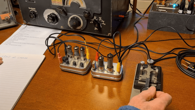
Challenging, perhaps, but by no means unachievable, as [Helge Fyske (LA6NCA)] demonstrates with this ultra-compact regenerative vacuum tube receiver. It’s a companion to his recent “spy transmitter,” a two-tube radio built in — or on, really — an Altoids tin. The transmitter was actually a pretty simple circuit, just a crystal-controlled oscillator and an RF amplifier really, but still managed about 1.5 Watts output on the 80-meter ham band.
The receiver circuit ended up being much more complicated, as receivers do, and therefore harder to cram into the allotted space. [Helge]’s used a three-tube regenerative design, with one tube each devoted to the RF amp, detector/mixer, and audio amplifier stages. As in the transmitter, the receiver tubes are mounted on the outside of the box, with the inside crammed full of components. [Helge] had to be quite careful about component positioning, to prevent interstage coupling and other undesirable side effects of building in such close quarters.
Was it worth it? Judging by the video below, absolutely! We’ve rarely heard performance like that from even a modern receiver with all the bells and whistles, let alone from a homebrew design under such constraints. It sounds fantastic, and hats off to [Helge] for completing his spy radio suite in style.
Thanks to [Stephen Walters] for the tip.


Really nice, but I don’t think this is a regenerative receiver. I think it is a direct conversion receiver. Great job Helge! Thanks and 73 Bill N2CQR
Three tubes could be up to 6 stages using that pin format if the stages can interact somewhat through internal capacitive coupling. There were even triple triodes
We are glass tubeway days now seem so unreal
Could we see a circuit diagram ? Was this receiver only designed for AM reception (no SSB) ?
He is using it only for CW, hence the fewer components!
There is a complete circuit diagram shown at the end of the video.