Tiny Three-Tube Receiver Completes Spy Radio Suite

In our surface-mount age, it’s easy to be jaded about miniaturization. We pretty much expect every circuit to be dimensionally optimized, something that’s easy to do when SMDs that rival grains of sand are available. But dial the calendar back half a century or so and miniaturization was a much more challenging proposition.

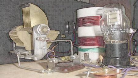
Challenging, perhaps, but by no means unachievable, as [Helge Fyske (LA6NCA)] demonstrates with this ultra-compact regenerative vacuum tube receiver. It’s a companion to his recent “spy transmitter,” a two-tube radio built in — or on, really — an Altoids tin. The transmitter was actually a pretty simple circuit, just a crystal-controlled oscillator and an RF amplifier really, but still managed about 1.5 Watts output on the 80-meter ham band.

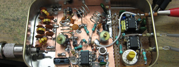
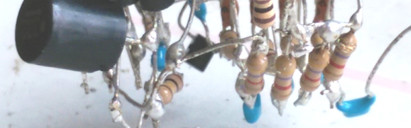
The receiver circuit ended up being much more complicated, as receivers do, and therefore harder to cram into the allotted space. [Helge]’s used a three-tube regenerative design, with one tube each devoted to the RF amp, detector/mixer, and audio amplifier stages. As in the transmitter, the receiver tubes are mounted on the outside of the box, with the inside crammed full of components. [Helge] had to be quite careful about component positioning, to prevent interstage coupling and other undesirable side effects of building in such close quarters.

Was it worth it? Judging by the video below, absolutely! We’ve rarely heard performance like that from even a modern receiver with all the bells and whistles, let alone from a homebrew design under such constraints. It sounds fantastic, and hats off to [Helge] for completing his spy radio suite in style.

Continue reading “Tiny Three-Tube Receiver Completes Spy Radio Suite”

Spectrum Analyzer With 555 Fits In A Tin

[VK2ZAY] has a thing for 555 chips. Before the ready availability of microcontrollers, the 555 was the hardware hacker’s swiss army knife. After all, even though the chip is supposed to be a timer, it is really a bunch of simple pieces you can use to make a timer: a pair of comparators, a few transistors, and a flip-flop. You can use those parts in many different ways, and a timer is just one of them.

[VK2ZAY] used one as a key component in a simple spectrum analyzer. The 555 generates a ramp voltage which alters the frequency of an oscillator. The oscillator mixes with the input signal and a fixed-frequency superregenerative detector creates an output voltage proportional to the input signal strength. You can see a video of the whole setup, below.

Continue reading “Spectrum Analyzer With 555 Fits In A Tin”

A Spicy Regenerative Reciever

We recently posted a three-part series about using LTSpice to simulate electronic circuits (one, two, three). You might have found yourself wondering: Can you really simulate practical designs with the program? This quick analysis of [QRP Gaijin’s] minimalist regenerative receiver says “yes”.

Continue reading “A Spicy Regenerative Reciever”

Radio Receiver Or Art? Why Not Both?

We’ve heard it said before that you should build things twice. Once to learn how to build it and the second time to build it right. [AA7EE] must agree. He was happy with his homebrew regenerative receiver that he called Sproutie. But he also wanted to build one more and use what he learned to make an even better receiver. The Sproutie Mark II was born.

This isn’t some rip off of an old P-Box kit either. [AA7EE] used a four-device RF stage with FET isolation back to the antenna and a regulated power supply. Plug in coils allow reception on multiple bands ranging from about 3 to 13 MHz. There’s an audio stage with multiple selectable audio filters, and–the best part–a National HRO tuning dial that is a work of art all by itself.

Continue reading “Radio Receiver Or Art? Why Not Both?”

Design Diary: Varactor-Tuned Regen Receiver

[QRP Gaijin] likes to build regenerative receivers. If you’ve ever built a serious one, you know there are (at least) two problems: One is you need a variable capacitor (hard to find these days). The other annoyance is that if you cover a wide frequency range, you probably need more than one coil.

[QRP Gaijin’s] latest radio design doesn’t have either of these problems. He uses a coil with a single pole double throw switch to bandswitch a single coil. There is no traditional main tuning capacitor. Instead a 1SV149 varactor provides the radio’s main tuning capacity (the diode tunes between 35 to 500 pF).

The post provides a nice design and a neat looking build in a Tupperware container (well… the outside is neat, at least; the inside is… best left inside the Tupperware). Better still, [QRP Gaijin’s] post details how he got to the final design, starting with the idea, and detailing the original design and the changes he made along the way. He also used data from an earlier build to limit how much the regeneration control has to be changed over wide frequencies and details how that changed the design. The prototype actually lacks the planned bandswitch, but will cover 3 to 30 MHz with the right coil.

There are certainly simpler regenerative receivers out there. However, the sophistication of this design along with the details of the designer’s thought processes makes this an interesting intermediate weekend project.

Continue reading “Design Diary: Varactor-Tuned Regen Receiver”

Simple One-Chip Regenerative Receiver

Crystal radios may be the simplest kind to make, but regenerative receivers are more practical and only a little more complicated. A recent design by [Selenium] is super simple because it uses a single LM386 audio amplifier IC.

You might be surprised that you can convert an audio amplifier to a receiver using just a handful of components (a variable capacitor, a coil, a handful of capacitors, and a speaker). However, [Selenium] realized he could subvert the gain and bypass pins to cause regeneration and wound up with a very simple receiver.

If you haven’t looked at regenerative receivers before, the principle is simple (and dates back to 1912). An oscillator is an amplifier that gets (theoretically) an infinite amount of gain at one particular frequency. A regenerative receiver is just an amplifier that is almost (but not quite) at the point of oscillation. This gives it very high frequency-specific gain and a measure of selectivity. You can also nudge the receiver just into oscillation to receive CW or SSB signals.

[Selenium] built his prototype on an old receiver chassis because it had the IC and the variable capacitor already in place. However, others have built successful copies on breadboards ([Austin Heller] created several good looking breadboard versions) and on PCB material. [Selenium] also released some other unique LM386-based designs that use more parts (and, probably, have better performance). Looks like a simple way to build a practical receiver.

Homemade Regenerative Tube Radio

There are no microcontrollers in this project. In fact you wont find a single transistor. This classic regenerative tube radio, modeled after an early 20th century homebrew is complete with schematic and additional photos. For those who are not familiar with tube designs and for simplicity, the regeneration circuit can be thought of as feedback though this relation may be argued. Read the rest after the break which includes a crash course in tube operation. Continue reading “Homemade Regenerative Tube Radio”