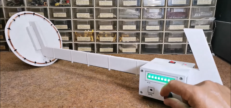
If you want to get rich by hunting with a metal detector, you might want to consider how much you invested in the hardware to start with. Finding a tin can with a $200 detector might not make economic sense. But building a metal detector yourself doesn’t have to be hard, as [Mirko] shows in a recent post. His STM32-based pulse induction metal detector looks good and works well, as you can see in the video below.
[Mirko] reports that the device can detect a coin at 30 cm and a large metal object at more than 80 cm. The project uses the Arduino IDE and a Blue Pill STM32 module. The project looks good with an LED module and a rotary encoder to set sensitivity.
Pulse induction metal detectors use a single coil to send and receive short pulses. This differs from the more common BFO-style which uses two frequencies that produce a beat frequency that changes in the presence of metal. These use two coils and are more affected by mineralization — the interference caused by minerals in the soil — and general interference. Typically, BFO detectors have less sensitivity, especially at a distance.
This isn’t the first pulsed induction detector we’ve seen. Of course, for a simple one you can — to forestall comments — use a 555.


Can someone explain how some of the more advanced metal detectors seemingly differentiate between junk (pull tabs, for example) and specific worthwhile metal objects?
Inside the Metal Detector: The First In-depth Book on Metal Detector Technology Since 1927 by George Overton (Author), Carl Moreland (Author)
https://amzn.eu/d/4rtR5gQ
IANAD (Detectorist)
I believe the base principle is that different metals have a different phase responses. For example a metal detector sends out a signal at a certain frequency, say 50kHz, different metals will return the 50kHz signal with different phase offsets. Although it’s not a perfect solutions since some cheap metals return similar phase responses as more desirable metals.
Others, please correct me if I’m wrong or omitting key info.
You got me curious and I found an advanced technique which uses the electromagnetic decay signature of the buried object:
Metal Detection and Classification Technologies
https://www.jhuapl.edu/Content/techdigest/pdf/V25-N01/25-01-Nelson.pdf
This forum would be the place to ask further about this subject:
https://www.geotech1.com/forums/forum/technology/tech-forum
It might be interesting to use a noise or sweeping generator to output a wide spectrum of frequencies from the head, then analyze the intensity/phase from the returned signal wrt frequency, then use an algorithm (AI?) to correlate and characterize the object.
[SARCASM] I go into the first menu under “settings” on the device and then press the option “sensetivity” on the third entry and set that to 80.[/SARCASM]
The following explains how my PI design discriminates and it has a diagram. https://www.wombatpi.net/better_discrimination.pdf
Every metal target has two features: Conductivity and Iron content. The conductivity is fairly easy to see because it affects how long the current ‘spins’ around in the target. An aud10c coin and a pulltab might ‘spin’ for 15uSec. A silver coin and a squashed aluminium can will spin for say, 100uSec. Think of them like ‘Fly wheels’ A very-conductive target is like a heavy fly wheel that takes a long time to spin-up and spin-down. A low-conductive is like a light-flywheel that spins up and down quickly.
hmmm… looks a lot like this one, but why change what works…
https://hackaday.com/blog/?s=metal+detector
hackster.io writeup, login required and I didn’t bother to check whether it also requires a paid subscription. So basically just monetization on another platform it seems.
Just checked, no login required, all materials available for direct download, what are you talking about?
Looks like the control panel changed.
They’re all made by the same person, but use fundamentally different technologies. The different technologies (plused induction, beat frequency oscillators, very low frequency) have different strengths and weakness depending on what you’re trying to detect, in what conditions and how much you like digging to find out that the potential gold nugget is actually a rusty nail. My biggest criticism of the author’s series is a lack of in depth discussion of the operation of the circuitry and their appalling schematic capture.
Keep in mind that in some EU countries it is illegal to own a metal detector unless you have a government-issued license – itself an unobtainium unless you’re an archeologist working in state institution. I wouldn’t risk 2 years in jail just to find some junk or WW2 UXO.
Which one? In Poland for example, you have to obtain land owner permission. Good luck with that if the owner is the state.
According to what I’ve googled up: Cyprus bans it, Germany requires a license, a bunch of other places require permission or forbid recovery of certain kinds of object.
When I was young and didn’t know enough about electronics, I found a schematic (kit?) for a metal detector.
It had two oscillators based on an inverter with the loop inductor somewhere in one of the circuits. The other was free running. The difference frequency would be sent to a speaker. At the time I didn’t have ANY equipment to debug why it didn’t work.
My current: ‘when I get around to it” (hasn’t happened in the last 20 years) project would be to make two identical oscillators, Have the loops “double-D” at the end of the stick. That should be pretty sensitive. Add a microcontroller and instead of running the detector loops as part of an ocilator you can measure the inductance (and phase shift?) with the microcontroller and do even more interesting stuff.
I have built several induction balance detectors as well as older tech (Transmitter/Receiver). Most of the information as well as Induction balance design can be found here;
https://www.geotech1.com/forums/forum
Hi Hector, where in the forum specifically? (i.e. Tech, tools, schematics, etc.)
It’s no Minelab, but it looks like a fun way to kill a weekend