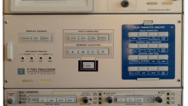
It’s normal today for even relatively modest instruments to have some form of computer control capability over Ethernet or USB. But five decades ago this was by no means a given, and when Tektronix shipped their P7001 digitiser module for their high-end oscilloscopes in 1971, they were initially designed to interface with a minicomputer. Not everybody has a PDP/11 lying around in 2023, but [Holger Lübben] wasn’t fazed by this. He set about creating a USB interface for this ancient piece of test equipment.
At its heart is a Teensy 4.1 which does the job of interfacing with the Tektronix 16-bit bus through a level shifting transceiver. The software for the Teensy comes with some demos, but sadly not the Tek BASIC of the original. We’re particularly impressed with the care to make the card frame for the module resemble as closely as possible an original Tektronix product.
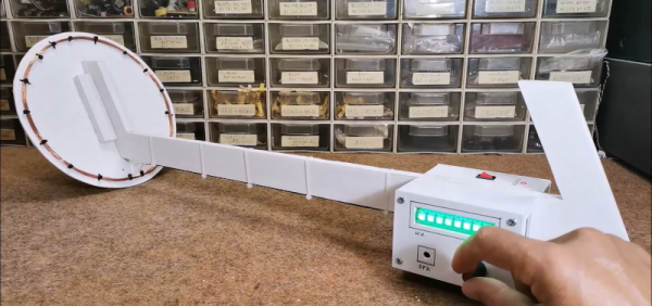
If you want to get rich by hunting with a metal detector, you might want to consider how much you invested in the hardware to start with. Finding a tin can with a $200 detector might not make economic sense. But building a metal detector yourself doesn’t have to be hard, as [Mirko] shows in a recent post. His STM32-based pulse induction metal detector looks good and works well, as you can see in the video below.
[Mirko] reports that the device can detect a coin at 30 cm and a large metal object at more than 80 cm. The project uses the Arduino IDE and a Blue Pill STM32 module. The project looks good with an LED module and a rotary encoder to set sensitivity.
More fallout for SpaceX this week after their Starship launch attempt, but of the legal kind rather than concrete and rebar. A handful of environmental groups filed the suit, alleging that the launch generated “intense heat, noise, and light that adversely affects surrounding habitat areas and communities, which included designated critical habitat for federally protected species as well as National Wildlife Refuge and State Park lands,” in addition to “scatter[ing] debris and ash over a large area.”
Specifics of this energetic launch aside, we always wondered about the choice of Boca Chica for a launch facility. Yes, it has all the obvious advantages, like a large body of water directly to the east and being at a relatively low latitude. But the whole area is a wildlife sanctuary, and from what we understand there are still people living pretty close to the launch facility. Then again, you could pretty much say the same thing about the Cape Canaveral and Cape Kennedy complex, which probably couldn’t be built today. Amazing how a Space Race will grease the wheels of progress.
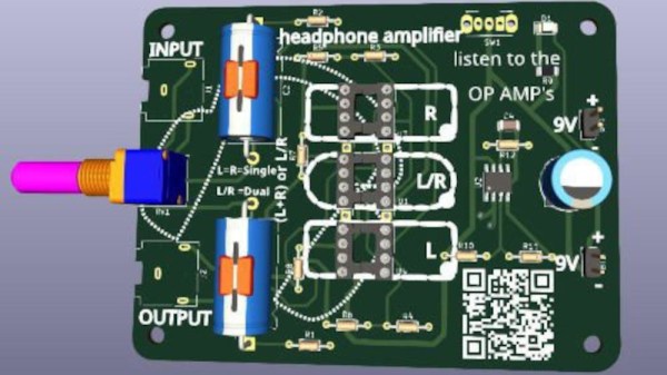
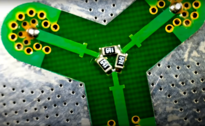
In the world of audiophilia there are arguments that rage over the relative merits of particular components. Sometimes this can reach silly levels as in the high-end ALPS pot we once saw chosen as a volume control whose only task was to be a DC voltage divider feeding a pin on a DSP, but there are moments where such comparisons might have a bit of merit. To allow the comparison of different op-amps in a headphone amplifier, [Stephan Martin] has created a stereo amplifier board complete with sockets to take single or dual op-amp chips.
The circuit is based upon a design from the 1990s which as far as we can see is a pretty conventional non-inverting amplifier. It has an on-board op-amp to create a virtual ground, and three sockets for either two single or one dual op-amp to create a stereo headphone amplifier.
So the burning question is this: will you notice a difference? We’re guessing that assuming the op-amps under test are to a sufficient specification with a high enough impedance input and enough output current capability, the differences might be somewhat imperceptible without an audio analyser or the hearing of a ten-year-old child.
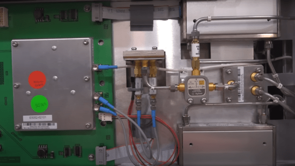
[Shahriar] of The Signal Path is back with another fascinating video teardown and analysis for your viewing pleasure. (Embedded below.) This time the target is an Agilent E5052A 7 GHz signal Source/Analyser which is an expensive piece of kit not many of us are fortunate enough to have on the bench. This particular unit is reported as faulty, with a signal power measurement that is completely off-the-rails wrong, which leads one to not trust anything the instrument reports.
After digging into the service manual of the related E5052B unit, [Shahriar] notes that the phase noise measurement part of the instrument is totally separate from the power measurement, only connected via some internal resistive power splitters, and this simplifies debugging a lot. But first, a short segue into that first measurement subsystem, because it’s really neat.
Cross-correlating time-gated FFT (TG-FFT) subsystem at the top, dodgy power detector at the bottom
A traditional swept-mode instrument works by mixing the input signal with a locally-sourced low-noise oscillator, which when low-pass filtered, is fed into a power meter or digitizer. This simply put, down-converts the signal to something easy to measure. It then presents power or noise as a function of the local oscillator (LO) frequency, giving us the spectral view we require. All good, but this scheme has a big flaw. The noise of the LO is essentially added to that of the signal, producing a spectral noise floor below which signals cannot be resolved.
The E5052 instrument uses a cunning cross-correlation technique enabling it to measure phase noise levels below that of its own internal signal source. The instrument houses an Oven-Compensated Crystal Oscillator (OCXO) for high stability, in fact, two from two different vendors, one for each LO, and mounted perpendicular to each other. The technique splits the input signal in half with a power splitter, then feeds both halves into identical (apart from the LOs) down-converters, the outputs of which are fed into a DSP via a pair of ADCs. Having identical input signals, but different LOs (with different phase noise spectra) turns the two signals from a correlated pair to an uncorrelated pair, with the effects of chassis vibration and gravity effects also rolled in.
The DSP subtracts the uncorrelated signal from the correlated signal, therefore removing the effect of the individual LO’s effect on the phase noise spectrum. This clever technique results in a phase noise spectrum below that of the LOs themselves, and a good representation of the input signal being measured.
This is what a DC-7GHz resistive power divider looks like. Notice the inductive matching section before each resistor branch.
Handily for [Shahriar] this complex subsystem is totally separate from the dodgy power measurement. This second system is much simpler, being fed with another copy of the input signal, via the main resistive power splitter. This second feed is then split again with a custom power divider, which upon visual inspection of the input SMA connector was clearly defective. It should not wobble. The root cause of the issue was a cold solder joint of a single SMA footprint, which worked loose over time. A little reflow and reassembly and the unit was fit for recalibration, and back into service.
That altitude is considerably short of what would be called “space”, but it’s still an awfully long way up and the air there is very thin compared to on the surface. Space is generally (but not universally) considered to be beyond 100 km above sea level, a human-chosen boundary known as the Kármán line. 35 km is a long ways into the stratosphere, but still within Earth’s atmosphere.
Even so, that doesn’t mean there haven’t been efforts to go considerably higher. There was a Japanese proposal to drop airplanes made from special heat-resistant paper from the International Space Station, roughly 400 km above Earth. Success would show that low-speed, low-friction atmospheric reentry is feasible — for pieces of paper, anyway. But one of the challenges is the fact that there is no practical way to track such objects on their way down, and therefore no way to determine where or when they would eventually land.
There have been many other high-altitude paper plane launches, but the current record of 35,043 meters was accomplished by David Green in the United Kingdom as part of a school project. Such altitudes are in the realm of things like weather balloons, and therefore certainly within the reach of hobbyists.
As for the airplanes themselves, the basic design pictured here probably won’t cut it, so why not brush up on designs with the Paper Airplane Design Database? Even if you don’t send them into the stratosphere (or higher), you might find something worth putting through a DIY wind tunnel to see how they perform.
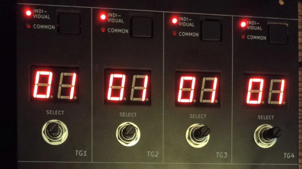
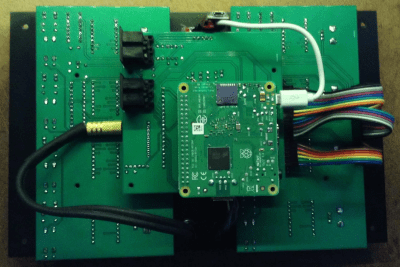
[Kevin] wanted to emulate the look and feel of the original TX816 aesthetic, developing a custom PCB handling the user interface for four of the eight channels, and a second acting as an interface to the Raspberry Pi using a Pico. Also sitting on this PCB is the GY-PCM5102 I2S DAC, and the MIDI connectors needed to connect to the system controller. Both PCBs, including a PCB-based front panel, were developed with KiCAD. The firmware for the Pico part of the system can be found on the firmware GitHub. The video demo (embedded below) shows off the system running a very 80s-sounding rendition of Holst’s famous ‘Jupiter’ from the planet series, and we all agree it sounds pretty sweet. For a complete rundown of the build, here are the links for the blog series for ease of access: Intro, PCBs, Panel, Build Guide, Mechanical, Pico/TX816 IO code, and finally usage. Phew!


 Pico. Also sitting on this PCB is the


