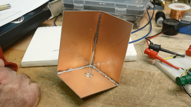
Sometimes antennas can seem like black magic. However, when you see things like a dish antenna, it sort of makes sense, right? Just like a mirror focuses light, the parabola of a dish focuses RF energy. But [IMSAI Guy] shows another common-sense antenna arrangement: a corner reflector dipole. He had built one years ago and decided to do a bit of research and make another one.
In a clever use of copper-clad board, he was able to make a reasonable reflector by soldering together three boards and an RF connector. A single wire makes the “driven element,” and by bending it to just the right position, you can change the characteristic impedance for matching.
The antenna, in this case, is essentially a quarter-wave antenna with a ground plane and reflector arrangement. After the obligatory chalk talk, he breaks out the vector network analyzer and shows how well it matches. He didn’t, however, measure the gain or directional selectivity due to the reflector.
Intuitively, you’d think this kind of antenna would be good for direction finding purposes. In fact, hams that use handy talkies for direction finding often use their bodies to block signals, much like these reflectors should.
The [IMSAI Guy] reflector is pretty small, but you can easily make bigger ones. Using PCB material for antennas isn’t anything new, either, but we still enjoyed this simple corner reflector build.


Great to see people experimenting with making antennas, rather than assuming they’re some kind of ‘magic’ and steering clear. It’d be worth learning to use a simulation tool like 4nec2 to get a feel for how antennas behave (not just impedance match but you can then explore the gain/pattern too). One thing to remember though: impedance match rarely matters much once it’s better than about 10dB RL – or even 6dB for some applications.
Absolutely agree, use 4nec2 for this (or virtually any) antenna to rapidly gain insight on antenna characteristics.
4nec2 is addictive! After you start using it, you will need to pry yourself away and heat up the solder iron!
73!
It would be great to see an amateur version of EMIT or HFSS for modeling.
I am interested in using genetic programming to evolve an antenna geometry by starting with the desired signal strength pattern and working backwards via iterative optimisation.
This reminds me of one time when I had no cell reception. There was a baseball field with a metal cage around where the batter stands, it looked like a large dish. I stood at the focal point of it, and surprise, had enough signal to make a call.
In outback Australia, there are dishes pointing to the nearest cell phone tower with a stand to place your mobile phone to get the best signal. Much cheaper than a tower for very low traffic areas.
How did you aim the batting cage toward the cell tower? And where did you attach whatever was the “driven element” to your cell phone?
It’s a passive repeater—no direct connection is needed.
I may have some copper sheet laying around. I’m wondering if something like this with my 5G internet box would improve if pointed in the direction.
We have a pcb milling machine at work and I have one at home, and this copper clad FR4 stuff that it uses is surprisingly useful as general fabrication material. We build all sorts of dumb stuff out of it at work. It’s nice if you have a mill because you can precisely cut the shapes, including with tabs just like plywood on a laser cutter, but once you solder them together you can make something pretty big, pretty quickly. We used ours to make, among other things, a camera mount for screenshots on an old network analyzer, and a whole selection of thermal boxes for temperature testing IC’s with a thermal forcer where we need material that can handle 150C indefinitely.
I’m thinking a soldered cyberpunkesque urinal made out of FR4. Bonus it could be cleaned with a wire brush instead of those dinky plastic ones.
A wire brush scratches copper though, and the standard weight is a 35 um thick layer.
It’s there, and then it ain’t!
+1 to that. FR4 is amazingly strong and versatile. The copper cladding makes it easy to solder together even very elaborate structures. Here’s a model of the Galileo spacecraft built with FR4. http://www.retrotechnology.com/galileo/galileo_1802.html
Check out Machining and Microwaves channel on YouTube. They are experimenting with 3d printed antennas which focus RF like a lens. Cool stuff.
What are the clear plastic rods on the back end of this radar detector supposed to do? http://www.radardetectormuseum.com/foxxk_1.html
Probably the dielectric waveguides for x and k band.
https://www.radardetector.net/forums/archive/index.php/t-25138.html
I’d guess they are microwave lenses. Dielectric materials (often plastics) will guide and focus microwaves just like the familiar optical lenses we’re used to. So rather than a large metal reflector, the feed antenna’s radiation might be focussed using a dielectric lens.
We used corner reflector antennas here for our packet radio network like…40 years ago?
Solid bottom plate and mesh walls
You can’t do anything about your provider throttling the wifi signal on on you for using too much data. A directional antenna may help a little bit. Your provider knows how many devices you are using. Build a one watt TV transmitter,
Plug your fire stick into the transmitter,
Tune your TVs to the transmitter. You can have a hundred devices but your provider will only see one device.
If providers quit playing the throttling game by reducing signal strength we won’t have to play these games.
you can get another wifi ap instead of the junk one they give (or sell) you. same job but works with all devices
Or move to a country where there are no bs data caps and throttling!
I joke, but also offer my condolences.
We also have junk oem routers here though.