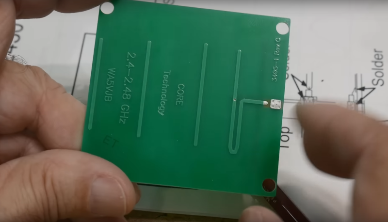
Yagi-Uda antennas, or simply “Yagis”, are directional antennas that focus radio waves to increase gain, meaning that the radio waves can travel further in that direction for a given transmitter power. Anyone might recognize an old TV antenna on a roof that uses this type of antenna, but they can be used to increase the gain of an antenna at any frequency. This one is designed to operate within the frequencies allotted to WiFi and as a result is so small that the entire antenna can be printed directly on a PCB.
The antenna consists of what is effectively a dipole antenna, sandwiched in between a reflector and three directors. The reflector and directors are passive elements in that they interact with the radio wave to focus it in a specific direction, but the only thing actually powered is the dipole in the middle. It looks almost like a short circuit at first but thanks to the high frequencies involved in this band, will still function like any other dipole antenna would. [IMSAI Guy], who created the video linked above which goes over these details also analyzed the performance of this antenna and found it to be fairly impressive as a WiFi antenna, but he did make a few changes to the board for some other minor improvements in performance.
The creator of these antennas, [WA5VJB] aka [Kent Britain] is an antenna builder based in Texas who has developed a few unique styles of antennas produced in non-traditional ways. Besides this small Yagi, there are other microwave antennas available for direction-finding, some wide-band antennas, and log-periodic antennas that look similar to Yagi antennas but are fundamentally different designs. But if you’re looking to simply extend your home’s WiFi range you might not need any of these, as Yagi antennas for home routers can be a lot simpler than you ever imagined.


looks more like a mono-pole though
fast forward to 08:06 to see how it’s a dipole. Hint, see the via in the active element
Yet, it is a proper directional 5 element Yagi-Uda antenna.
WA5VJB has been doing this for a very long time.
You wouldn’t download an antenna
Downloading often is terrible. D.O.I.T.
We have one for our CellSol setup that does 900MHz, you can download it here:
https://github.com/RbtsEvrwhr-Riley/CellSol
It’s a bit more clever in concept, in that it uses the fact that 4 layers boards are cheap now and creates a sort of a coaxial cable within itself.
Check out the whole project at https://f3.to/cellsol if you like :) I think it’s been on hackaday before.
Interesting, I’m working on a project that uses 915MHz LoRa. I don’t see documentation of that antenna design on your website, just the gerber files. Would you care to share some details, how have you found the performance? I’m also curious as to how you designed and tested it.
Most of the big old-skool TV antennas are log-periodics.
LP are wider bandwidth and lower gain.
Superficial similarity, but a log periodic is not at all a Yagi-Uda antenna.
Nobody calling out IMSAI guy on his hilariously wrong depiction of the signal profile on the antenna element? (in the thumbnail/preview image and at 5:25).
Is it current? is it voltage? Nope and nope. He’s drawing a full wave where it should be a half wave. He doesn’t really understand how this works.
Yagi with IFA antenna as radiator. The shunt to GND is positioned so the fees point sees around 50 ohm. That’s why return loss is that good. Cheers!
Is there an open source design tool that will let me define the signal strength values on the surface of a sphere then give me an antenna configuration that would generate the same pattern? If not does anyone have a reference for calculating this by hand?
Hmm… Could you add 100 directors, and 100 reflectors?
I have only seen designs with one reflector. You could add many director elements, but you get diminishing returns. I think each element after 5 increases the gain less than 1dB.
I built one with 12 or 13 elements for 2.4GHz. It was about 1m long as I recall.
Kent is a fantastic guy and has forgotten more about VHF/UHF/microwave antenna design than any five of us ever knew. I’m still using a collinear vertical he designed for 1200 MHz made from a piece of brazing rod. Works great.
I’ve actually used hundreds of these I bought from Kent over the years in a production environment, but with a very different goal – I used them as BLE4 receiver antennas and oriented them perpendicular to the transmitter! In this way, I was able to greatly reduce the range as opposed to increasing it. Kent worked with me on the concept, really turned out well – Kent taught me a ton, great guy, very interesting!
I’ve wanted to do circuit board antennas for a while. I actually have a handful of tabs open with different designs and some design recommendations. I instantly recognized the Yagi in the image (Yagis are my favorite antennas), before even reading any of the text. That’s awesome!
Honestly, I wish I had time, funding, and equipment to do some antenna research myself. I would really like to try to develop some non-traditional designs myself. Modern electronics constrains itself at a rather extreme level, mainly in the name of convenience, and I think we are missing huge amounts of potential in doing so. Nothing new will ever be discovered if everyone keeps thinking inside the box.
The plural of antenna is antennae bruh