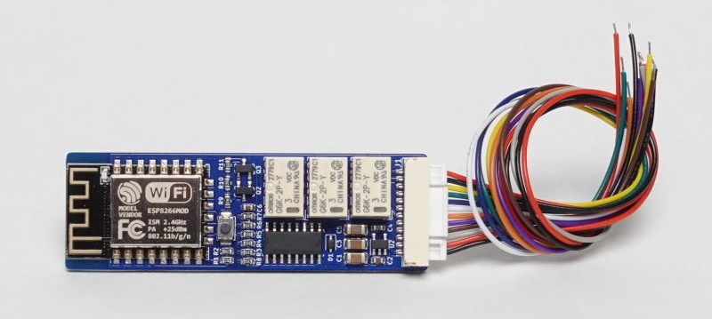
Integrating non-smart devices into your home automation system can be a cumbersome process, involving the wiring of multiple modules. However, [Pricelesstoolkit] has created the ESPClicker — a compact, ESP8266-based module that can remotely “press buttons” and simplify this process.
The ESPClicker’s core feature is its three relays that can be soldered to the button terminals of any existing “dumb” device, as [Pricelesstoolkit] demonstrated with his coffee machine in the video after the break. One of the relays can also be configured in the normally closed configuration. A compact twelve pin connector provides a removable wiring interface for the buttons, additional relays, power and even a contactless power detector that can be wrapped around an AC wire.
[PricelessToolkit] has done several Home Assistant related projects, and we recently featured his little Home Assistant controlled guardian bot. We’ve also seen other project that make use of ESPHome, like a iPod style scroll wheel and a LEGO train set.


I had this idea a few years ago. Also I thought it would be cool if manufacturers were required to provide a pin header for buttons on device or serial port with simple commands so if adding IOT was not in their budget it could easily be enabled as a feature addon for sale/hack.
I think many of us had this idea, but this guy made it real. However, I wanted to not use relays to make the device smaller (and because I didn’t know about these super compact relays). For a circuit like a coffee machine, maybe only transistors would be needed.
The pin header thing exists, though I have never seen it on consumer products but only on professional devices.
I am working on something very much like this, using cheap optocouplers – works for so many devices where it’s not processing a lot of power through the switch.
Please make it 4, 8 and 16 button versions – 3 are not enough for all appliances.
I fully agree with you here. But I don’t think adding more relays is the correct solution. At some point, this really doesn’t scale well — even if it’s just wire management that becomes quite awkward once you need to tie into this many buttons.
Turns out, most appliances use GPIO (or similar) inputs, only if they have a really small number of buttons. And that’s what this board works well with.
But if your appliance has dozens of buttons, it almost certainly implements a key matrix. And it makes a lot more sense to tie directly into the matrix than into individual buttons. I have had good luck with two 4052 style multiplexers operating back to back. If you need to drive anything bigger than a 4×4 input matrix, things get a little more complex, though. But fortunately, most consumer devices that I have encountered fit these constraints (or there already is a better way to achieve what I want to do).
The ESP8266 doesn’t have very many GPIOs. If you wanna drive a lot of relays then your best bet is to get a board with a bunch of them driven by a shift register or I2C or something. They’re super cheap. Or you can design your own integrated board like this guy did.
I hacked my sharp ceramic heater to manipulate the buttons on it. I was going for a proper thermostat since this was before I started my smart home setup, but I just used transistor for that. The buttons all get pulled low, so it was quite simple. I may have done something slightly wrong, cause I would occasionally get ghost activations, so I backed it up with photoresistors next to the built in LEDs to keep things where they should be. Works well.
I think USB-C is a perfect connector for this, there’s already alternate modes. Just use Dallas One Wire over SBU, the way they should have just use One Wire for CC negotiation….
That’s a good idea
What I find more ridiculous is that I just had a look on AliExpress and you can get similar for €2 (about 4 incl shipping). I know these guys have the form factor nailed down, but €35?! I’d rather get the €4 module from Ali and mount it on an external box.
Here’s an example of a 1 channel version:
https://www.aliexpress.com/item/32845077134.html
Your Ali express item only has 1 relay (double throw, so 2 buttons) and doesn’t include the ESP32 module, which is most of the cost.
I think the point is that these are fun to design and build, not a matter of min-maxing cost and utility.
While useful for other things, relays are about the most useless component for a smart home.
All’s a relay is is a switch that can be controlled remotely and make up a huge chunk of all smart components.
Can you explain you’re reasoning? Id say relays are one of the most useful components for a smart home. Most people want to turn things on and off, open/close garage doors, simulate other simple button presses.
Lol, how else would you bridge your smart home to control devices that don’t integrate and only have buttons to press? It’s literally the only way, and the topic of the article.
Use a MOSFET and have it go bang when you forget it’s not rated for the load.
Of course I’ve never done that. That skidmark on the case was there all time.)
The issue with MOSFETs and the reason I prefer relays is the form C contact. I use the NC contact just as much as a NO contact, probably more.
I actually end up having to buy relays just to NOT and out put from a manufacturer.
If you want to argue reliability then just switch to small form replaceable ice cube relays. IDEC makes some that are close to the same size. Honestly being able to pull the relay is great for troubleshooting.
I’ve used optoisolators for this task to keep things solid state while also keeping my control circuit isolated from the main device. Relays are nice and cheap but do have a finite lifecycle and switch cycle time. The relays used here also have the problem that any interruption in power to the control device maybe unintentionally cycle the relay leading to unknown results on the controlled device. Bistable relays would solve for that and I’m a little surprised they weren’t applied here for that reason.
110v 100W+ AC optoisolators are a lot harder to come by than relays.
Sure, 110V supply voltage optoisolators are hard to find, but that’s not what luma’s talking about. They’re talking about activating buttons on an appliance, not emulating light switches. No reason to use a bulky, noisy, expensive relay for that when $0.60 will get you 4 optocoupled signals.
Relays are great! They just aren’t necessary for everything.
You are literally replacing a mechanical seitch with a relay. Why would you mention lifecycles?
I’m curious as to why relays would be considered useless too? They’re about the best solution I can think of for switching high voltage devices with low voltage signals. You can use solid state solutions, but as far as I’m aware when they go bad they can take out your controller with a high voltage short.
Every smart plug I have uses a relay, I can hear them click when they change states. My smart lightbulbs use an IC. I suspect mostly because LED bulbs are generally pretty low current and we have an expectation that bulbs blow. You don’t want that happening to your smart TV.
Which is the reason you’ll never design anything useful. What else would YOU use that can accommodate anything that needs to be switched?
Would have saved me the header pin jumper wire mess between my ESP32 board and the relay board that operates three garage doors.
‘… relays are about the most useful component for a smart home.’
Ftfy.
The biggest problem with relays is their limited life time (100 K cycles typ) and intrinsic unreliability. It is only because they are an inexpensive solution that they are so popular.
While relays are mechanical and therefore more prone to failure than solid state, the truth is relays are not as unreliable as people think. The problem is everyone “knows” how to use a relay so many of them are used improperly. For example, gold contacts offer low resistance but pit when switching high current “wet” which leads to failure. Coatings that won’t pit have higher resistance and — if used at low currents — will corrode and fail. Turns out the arc that pits the gold also cleans the hard material of corrosion. So you have to understand the current you are switching, if it is dry/wet and other factors. So properly used relays are reliable enough to work in military and space applications, but slapping random relays into random circuits is likely to be far less reliable.
Time to write an article on how to use relays then ;)
I’ve never actually seen a relay fail. Probably because 100k is decades of most consumer applications. I prefer solid state, but I don’t complain about relays as much as I complain about, say, a switch or a rotary encoder or a pot that really does fail unless it’s high end.
The only problem I can see is that an increasing number of devices use capacitive buttons (my coffee machine for example).
Outside of a robot to press the buttons, not sure how else to automate the unit.
I have successfully used two back-to-back 4051 style CMOS multiplexers to operate key matrices. This won’t work directly with capacitive buttons. But since these CMOS chips act as analog switches, I suspect the technique could be adapted relatively easily. Instead of directly connecting the two multiplexers back-to-back, you would need to put a small capacitor in between.
Stick some metal tape over each switch location. Use a transistor or MOSFET to connect the piece of tape to ground when you want to activate the switch.
I’ve automated cap buttons by using relays before, so this is still viable.
I use 2 homemade ESPHome devices like this to control our dumb heated mattress pad. It allows us to remotely preheat the bed, which definitely saves on heat, and allows us to have them automatically shut off when we want them to.
Smart mattress pads are expensive and every heated mattress pad I’ve had wears out over time. Makes more sense to buy a cheap dumb one every 3 years.
Nice solution (until someone tries to run mains voltage through it), but I think these days half the situations where this would be used could prolly be solved with one of those Tuya (…) wifi/zigbee sockets that also sense power load
Many of these small relays are perfectly fine when used with mains voltage. It is common for them to be rated up to 250V or more.
The PCB design should probably be changed to do so safely, though. But that’s easy enough to do, if it matters for your application. Just make sure to keep low and high voltage areas separate from each other and add appropriate safety devices as applicable (fuses, MOVs, TVS, gas discharge, …).
Of course, if you then plan on switching high power devices with high inrush currents or inductive loads, you need to do your homework and find a different type of relay. But that’s all certainly doable.
Or, you could simply buy one of the many of-the-shelf products that already exist for those type of devices. But for hacking small appliances and making them “smart”, this design looks fine. It fits a nice niche and does a good job emulating key presses.
I want to say thank you to @Danie Conradie for this post, and of course to those who support my work. Thank you very much! 🤗
Esp32 would be better thought, as it can do BT so you can control it directly if wifi is down.
Not really likely an issue – IIRC this is all local network. “Wifi is down” has come to mean “my internet connection is down”.
Wifi doesn’t often go down unless power is out, in which case the device you’re switching is likely also out of power. I can’t remember when my Wi-Fi network last actually went down.
OUR wifi has been down before. Not just the internet connection, but the ENTIRE network. It drops every(?) device off the network and it has to be reset.
I’ve actually wanted the reverse of this type of device for some time, as I have a 230v relay that when operated I need to translate into a web GET request over wired LAN. As I have a plan to install 9 of these in different locations each with an existing local LAN switch but without WiFi, I wanted to avoid WiFi-only modules so that I didn’t have to buy 9 access points as well.
Nothing readily available, so I’ve built my own circuit using a W5500 based RP2040 with PoE splitter providing data and Micro USB power, and an off the shelf (eBay) optocoupler/optoisolater to convert the 230v trigger to 3v3 signal on one of the GPIOs.
Works really well, and BOM should be close to £50-£60 each. I may put the schematics and MicroPython code on GitHub eventually.
Could you not use this https://www.shelly.cloud/en/products/shop/shelly-pro-1pm leave the relay itself closed and use the power monitoring feature to run your GET? I know it’s not as fun as rolling your own, but it’s a pretty polished and scriptable solution with an ESP running the show.
Thanks for the suggestion! I guess so, although it’s not particularly obvious that it can do that off the bat (but you’re right, it probably can) – hopefully the power monitoring would be sufficiently accurate to detect a sub 1-second pulse, without false triggering.
However the DIN-rail form factor isn’t actually ideal for my scenario, that would require the installation of a mini consumer unit (or similar) in each location.
I’m also not that familiar with the Shelly eco-system to be honest (ie. not at all), but presumably it’s cloud based which would be another issue (show-stopper, actually) as my use case would be in a commercial environment, and remote monitoring is another requirement (regular heartbeats etc).
If only they had something that accepted up to 230v AC as a momentary input trigger, 802.11af PoE powered, wall mountable and with a local API, it would be perfect! 😀
The UI, and even the programing, in most consumer stuff absolutely sucks, so in that sense this is a terrible idea.
For example of bad programming, I have a bread machine, that has started to glitch – it resetes just after it starts baking. That’s solveable if I intervene, because it has a deidcated ‘bake only’ program. The problem is, whoever coded this, told the machine to check that the temperature is <40C before it will do anything at all. So, you can'r start the baking program on an already-hot machine. Nuts.
I'm quite sure everyone can think of an example of terrible UI.
The fact that controlling buttons with relays is pretty much the only way to add (or bypass) 'smarts' on most devices is a damning testament to the industry.
Devices should be required to add some kind of standardized control interface, and at the lowest level possible.
Too bad this doesn’t also have switch INPUTS that can trigger home automation events. I’ve had a number of situations where I would have liked to provide a button (or detect a button press in an appliance) to trigger a sequence of events.
Google down again?
https://randomnerdtutorials.com/esp8266-wi-fi-button-diy-amazon-dash-button-clone/
The primary link should go to github and not youtube
I’ve done something like this take control of a ceiling fan/light remote. I would suggest adding a minimum amount of hardware debouncing (RC) so that user doesn’t inadvertently cause high frequency cycling of end device and potentially arc-weld contacts of parent device.
We all like DIY, of course, but this is one time when it really isn’t worth it. On, say, Amazon, search for “wifi relay module” and you’ll get loads of compact and inexpensive options. Like, a four channel (four relay) ESP-01 based board for $13. Assembled! The ESP-01 plugs in, so you could cheaply & easily swap it out for something more capable if you feel the need. Spend your time programming instead of messing with commodity hardware, and save the hardware tinkering for projects that actually benefit from it.