If you’ve done any development on USB hardware, you’ve probably wished you could peek at the bits and bytes as they pass through the data lines. Sometimes, it’s the only way to properly understand what’s going on. [ataradov]’s USB sniffer is built to do just that.
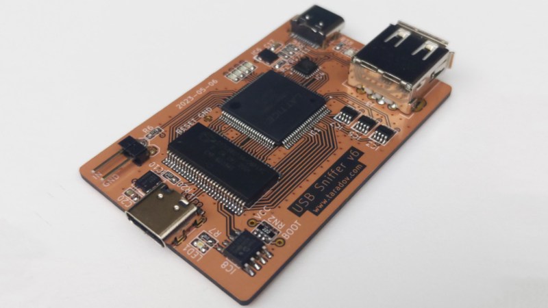
To sniff high-speed USB communications, the device relies on a Lattice LCMXO2 FPGA and a Cypress CY7C68013A microcontroller, paired with a Microchip USB3343 USB PHY. This setup is capable of operating at data rates of up to 40-50 MB/s, more than enough to debug the vast majority of USB peripherals on the market.
The device is built specifically for use with Wireshark. Most commonly used for network packet sniffing, Wireshark can also be used with a wide variety of other capture hardware for other debugging tasks, as seen here. In addition to live sniffing, it also allows captured data to be saved for later analysis.
If you need this tool, spinning up your own is straightforward. Gerber files are available and the required components can be bought off the shelf. Once assembled, you can program the chips via USB, with no external hardware programmer required.
We’ve seen some other similar hardware before. Meanwhile, if you’re whipping up your own useful debug tools, don’t hesitate to drop us a line!


USB is as bad as transitting data over Cascading interface used in older Macs. Hopefully it’ll be replaced by something that’s open like DB9 serial port.
not sure if trolling
Sniffma balls. lmao
Good luck getting 480Mbps or even more over an UART… However i agree that USB is quite difficult to master for hackers; and even for users all this naming stuff with USB3 is confusing.
Fair point but tbh that all depends on the assisted parallelized data propagation mechanism. I had a Hyperspectral Superbus interface which achieved asynchronous data compression and transmission, enabling ultra-low latency USB connectivity with multidirectional quantum coherence.
Has anyone tried using a Raspberry PI 4 with software like https://github.com/blegas78/usb-sniffify for usb sniffing?
I remember a similar project for Beaglebone Black back in the day.
usb-proxy?
https://hackaday.com/2015/12/23/usb-proxy-rats-out-your-devices-secrets/
https://github.com/usb-tools/USBProxy-legacy
The above are old, obsolete, abandoned.
This one seems to be relatively new, and may be more useful: https://github.com/AristoChen/usb-proxy
The CY7C68013A’s only “kindof” a microcontroller. I mean, it has a microcontroller in it, but it’s really a USB interface chip. The USB-to-custom interface runs completely independent of the actual 8051 microcontroller in it.
And it looks like the USB pair’s run straight from the connector to it without any ESD diodes? If so that’s a *really* bad idea. Those chips are wacko sensitive to stress on their USB lines: I literally have an entire drawer full of dead FX2 chips. It’s a pain in the neck because they seem fine for like *years* – and then they lose their ability to do high-speed USB, and then they just go deaf on the USB interface.
Even extremely expensive National Semi boards compatible with LabView don’t have any protection on USB. Yes, we have a pile of dead ones.
Yeah, I was convinced I was doing something weird in the design I have until I ended up with a failed FX2 on a TI development board that was in a long-term test setup have the exact same symptoms and eventually went dead. I can’t even say that adding TVS diodes would necessarily make a difference, but at least then I’d be able to tell Cypress/Infineon that there’s something else going on.
We just added USB2.0 high speed isolator and that has resolved out problems. But beware of full speed isolators. LabView tends to fall apart with these if it can’t transfer a burst of data in time.
Yeah, I *cannot* figure out why there’s such a huge variation in success rates with those chips. I’ve known plenty of people who say they’ve used them a ton and never had a problem, and I’ve just watched multiple designs slowly die one-by-one in the field over the past decade. Cypress (well, Infineon now) failure analysis always responds the same way: electrical over-stress, damaged transceivers.
Then again it’s not like you typically leave a cheap logic analyzer plugged in for multiple years, so who knows. It’s definitely not a short-term issue, they all worked for multiple years continuously before I even saw one fail.
I’m not a digital signal expert here, but isn’t a bus pirate better in that it can do what this does, and can also do a lot more?
Bus pirate can’t do this. A lot of logic analysers can handle low speed and full speed, but are a bit ungainly. High speed (USB 2.0) requires some more expensive hardware, though ~$100 devices have been coming available recently. USB 3.0+ still is the domain of ~$5k+ devices from vendors like Total Phase and Ellisys.
Personally I would encourage folks to wait for Cynthion, which is also open source with more capabilities and a growing open source ecosystem, but more people playing with USB and making tools is not a bad thing.
Bus Pirate can’t manage 480 Mbit/sec speed. Even just its uplink to your PC is only 12 Mbit/sec speed. The documentation says “Max speed is 12MBPS, but a realistic limit is 1MBPS”.
There’s also the matter of phase locking to the sync field which begins the transmission of each USB packet, so you can actually capture the bits within that packet. With today’s technology, this is the realm of dedicated hardware. To do it with a software defined interface, you’d need to sustain sampling of the signal at several GHz.
Signal level at 480 Mbit/sec is fully differential, nominally ±400mV. Normally 3.3V or 1.8V single-ended logic input won’t work. Even if Bus Pirate were hundreds of times faster, you’d also need to add a differential receiver circuit.
Thanks guys, I had a hunch I was missing something. When I checked the bus pirate specs, it claimed to do 40mbps, but obviously I missed something. That also explains why this seems to use much more expensive chips!
How does this differ from just using the USB features built into wireshark? Surely that’s an easier way as it is just a piece of software, you just plug the device into your PC and record all USB communications and then filter it to find the device you want.
Does this do something that wireshark can’t already do?
USB capture on your PC is usually good enough for the common uses of reverse engineering USB devices or troubleshooting code running on a USB device microcontroller.
But Wireshark using your PC’s USB port can’t help if the communication is between a USB device and some USB host other that your PC. For example, when I wrote the USBHost_t36 library for Teensy 3.6 and 4.1, I leaned heavily on a Total Phase Beagle 480 analyzer to see what communication was actually happening between Teensy and USB device, or USB hubs and then downstream devices. You also can’t observe communication such as between an Apple iPad and a SD card using the camera connection kit. They wires simply don’t connect to your PC, unless you use dedicated USB capture hardware.
USB capture with your PC’s hardware also can’t show you finer details of the actual USB communication, which are handled automatically in the USB host controller hardware on your PC. For example, when communicating with a 12 Mbit/sec USB device which is plugged into a USB hub, you can’t observe the split-start and split-complete tokens exchanged between your PC and the hub. Other fine details, like the number of NAK tokens or whether a high speed device replies with ACK or NYET token are also handled automatically by PC hardware and generally not visible to software on your PC.
USB capture devices usually provide precise time stamps on every captured token. Some of them offer digital input signals which can be captured alongside the USB communication. When accurate timing matters, USB capture devices also allow you to use a separate computer to capture and display the data, so you’re observing the accurate timing without placing additional burden on the PC acting as the USB host.
Admittedly, these are pretty niche usage cases. For the most common uses of reverse engineering communication of commodity USB device, or troubleshooting USB device (not host mode) code running on known-good microcontroller hardware, software capture on your PC is good enough. But you did ask what wireshark running on your PC can’t do. These are the special and more detailed USB capture scenarios where you really need dedicated USB capture hardware.
You reminded me of some gear we had for analysing Networks (Net XRay?).
Plug in a cable that was going to a router, add second cable to router, and monitor all traffic. Ethernet and optic fibre modules, for your choice of PHY. In our case (from memory), it detected excess traffic to a port, so we changed the network layout to compensate.
This reminds me of the Openvizsla project from a few years ago.
I wonder if Sigrock [1], plus the PulseView front end [2] would work with this device instead of Wireshark?[3] Sigrock already works with a bunch of logic analyzer hardware.[4]
* References:
1. Sigrock
https://www.sigrok.org/wiki/Main_Page
2. PulseView
https://www.sigrok.org/wiki/PulseView
3. Wireshark
https://www.wireshark.org/
4. Sigrock Compatible Logic Analyzers
https://www.sigrok.org/wiki/Supported_hardware#Logic_analyzers
I’m still looking for an affordable USB and/or SATA filter/firewall device. I really want to be able to block disk writes at a near-hardware level, and similarly authorize _specific_ USB device types rather than risking the widget having undeclared functions, benign or otherwise. The products I’ve seen for that purpose are sold to security and forensic companies for prices suitable when you’re going to bill customers for your services; I want something I could afford to slap on a number of small machines in my home network and/or add to my USB travel kit.
Logging is a great debugging tool, but I want to control the traffic.
Actually this “cheap USB sniffer” works exactly the same as expensive commercial products like the TotalPhase Beagle USB 480 and the ellisys USB Explorer 200.
Now do the same with a USB 3 phy and a cheap USB 3 bridge like the CH569W or the FT601.
Well, ok, the expensive commercial products might have a RAM chip for buffering.
Looks great, good job! Those commercial analyzers are crazy expensive…
Thanks, never heard of TotalPhase before, but as IO said, I’m not a digital signal analyst.
Does that then mean that you could this in lieu of a bus pirate? I’m not sure if bus pirate is multi channel, and I assume this is single channel.
Looks like a good project to try out…
IC8, how big does this EEPROM need to be? There is no part number for it… my guess is a 24LC32 4K device, based on .bin size and the Address strapping.
Part recommendations for J1, J2 and J3 (eg. footprints)?
What would you guys use to try to sniff the communication between an industrial HP series 4200 3D printer and his build unit?
Hi, I have 2 questions related to the topic, if anybody knows the answers:
1) do you know any dev kit ready to buy with Xilinx FPGA and the same USB3343 chip?
2) any FPGA source code in VHDL to manage implement USB SIE with ULPI interface?
There are no ready-made development kits available. It is recommended to use an FPGA board (AX7201) + a custom USB3343 module connected via expansion ports. https://www.flywing-tech.com/“