The more accomplished 8-bit microcomputers of the late 1970s and early 1980s had a dedicated display chip, a CRT controller. This took care of all the jobs associated with driving a CRT display, generating the required timing and sequencing all the dots to make a raster. With a CRT controller on hand the CPU had plenty of time to do other work, but on some cheaper machines there was no CRT controller and the processor had to do all the work of assembling the display itself.
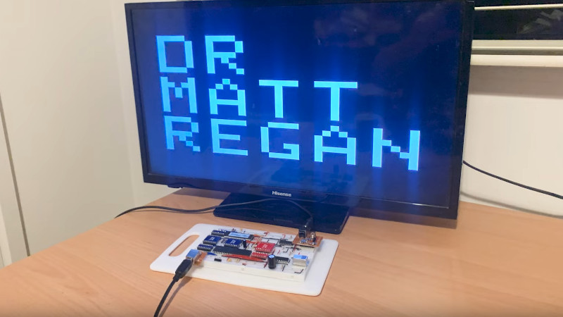
[Dr. Matt Regan] had a Sinclair ZX81 which relied on this technique, and he’s put up the first of what will become a series of videos offering a deep dive into this method of creating video. The key to its operation lies in very careful use of timing, with operations executed to keep a consistent number of clock cycles per dot on the display. He’s making a very low resolution version of the display in the first video, which he manages to do with only an EPROM and a couple of 74 logic chips alongside the Z80. We’re particularly impressed with the means of creating the sync pulses, using opcodes carefully chosen to do nothing of substance except setting a particular bit.
This method of assembling a display on such a relatively slow microprocessor has the drawback of no means of creating a grayscale, and of course it’s only available in glorious black and white. But it’s the system which gave a first experience of computing to millions, and for that we find the video fascinating. Take a look, below the break.
If this has caused you to yearn for all things Sinclair, read our tribute to the man himself.
Thanks [Philippe] for the tip!


It feels a bit like using the Z80 as a binary counter and actually doing PAL from the EEPROM but interesting anyway.
I’m working on my first Z80 computer but I ended up using a 128×64 LCD. I don’t know if I will ever try doing PAL in the future, I imagine that at least a dedicated framebuffer RAM is needed, and write to it only during VBLANK/HBLANK or something like that
well, at some point in the future he’ll doubtless be using an interrupt to trigger the video, so the processor will be able to run code between interrupts.
or ignore the problem so there are glitches on the display when the processor accesses the frame buffer, like CGA or the H-19 terminal.
You’ve missed how it works, then. The Z80 IS used as a binary counter, although it adjusts the count as necessary to create the RAM addresses. All the EPROM does is tell the CPU when to just keep counting and when to skip to a different address. And it also incidentally handles the counting necessary to generate the H & V sync pulses. This means that if you have the CPU doing anything else, there won’t BE any hsync or vsync to interrupt from. In the Sinclair ZX systems, the screen went completely blank when running a program, except when the program paused for user inputs. And even then, as the video shows, just processing the keystrokes interfered with video generation.
” In the Sinclair ZX systems, the screen went completely blank when running a program, except when the program paused for user inputs. And even then, as the video shows, just processing the keystrokes interfered with video generation.”
Not true. This was only the case with the ZX80, the ZX81 had also slow mode where the screen stays visible all the time.
In slow mode, programs were only executed during retrace periods, when video was blanked and the CPU had some spare time.
If you *chase* the beam, wouldn’t you always be late? I’ve always heard this concept called *racing* the beam, i.e. getting everything ready just ahead of the beam.
Correct. “Racing the beam” is most strongly associated with modifying the display after a frame starts, but before end of frame.
Most strongly associated with Atari 2600 and 400/800/XL/XE. Other systems used the technique, but Atari intentionally clocked the 6502 to EXACTLY 1/2 the speed of an NTSC signal, to lessen the calculation/effort needed to change things on the fly.
You could easily achieve dozens of colors on the Atari 800, without flickering. If flickering was ok, you could get 50+ colors onscreen (but there wouldn’t be much CPU left after this)
I think of https://en.wikipedia.org/wiki/TV_Typewriter as the canonical DIY video terminal book, but I’m pretty sure there was a later publication that used all the tricks to get a processor doing the work, such as reading a row of memory to get it to appear on the video data bus.
that would be “the cheap video cookbook”, also by don lancaster.
That is correct. Lancaster used a very simple computer design that used a Z80 CPU, an EPROM, an SRAM chip or chips, and what he called a “downstream tap”, which latched whatever was on the data bus at a given point into a shift register that produced the video signal. This was 1-bit per pixel, and the EPROM code produced composite sync at the same time, using an address line, I think, which was summed with the video signal using resistors to get the proper voltages for each.
I don’t recall exactly how he was able to get data into the SRAM, but I do remember that there was time, I think following generation of the hsync and vsync pulses, when the CRT beam would be off the screen, and you could execute any code you wanted. BUT, your code had to use exactly the right number of clock cycles in order to maintain sync, no matter what it was doing.
I’m not completely sure of the timing between the release of The Cheap Video Cookbook and the ZX-80, but I recall reading about the ZX-80 after I had read Lancaster’s book, and thinking that the ZX was inspired, if not outright copied from it. I specifically remember telling a co-worker of mine (we were both electronics technicians at the time) how the ZX worked, based on what I had learned from Lancaster. Of course, the Atari 2600 came out long before that, and also before The Cheap Video Cookbook, so the whole idea was not original with Don Lancaster.
Wow! https://archive.org/details/Cheap_Video_Cookbook_Don_Lancaster
Copyright 1978, so yeah, before the ZX80.
I’ll have to look at it a bit to see how accurate my memory was..
Yup, I definitely got some things wrong: he used a 6502 (a KIM-1 system) in his design, not a Z-80, and it was not a downstream tap, but an upstream tap, that took the SRAM output during fetches from EPROM. Most of the code was NOP instructions, which caused the address to be incremented and nothing else, but the upstream tap allowed the video shift register to capture the SRAM data, even though the CPU wasn’t even reading it.
Also, Sinclair would have had to make a number of changes in order to make this work on a Z-80, so clearly not a direct copy.
Back in 90s in Russia we were making custom ZX Spectrums. All kind of variations. Most of them were wired “directrly” to RGB in TV. It was easier to add a controller to existing CRT TV, than to mess with RF signal.
Also anyone who brought original ZX Spectrums had to use PAL-Secam converters.
“Back in 90s in Russia we were making custom ZX Spectrums. All kind of variations.”
I heard about this while reading about computing history of the former GDR. The IT guys in GDR weren’t really happy to being forced to switch from KC85/87 to producing primitive Spectrums, due to their popularity in the UdSSR..
“Most of them were wired “directrly” to RGB in TV. It was easier to add a controller to existing CRT TV, than to mess with RF signal.”
I assume that also was because of the weird eastern block TV/Radio frequency spectrum. Perhaps the standard RF modulator did use frequencies those TVs couldn’t handle?
“Also anyone who brought original ZX Spectrums had to use PAL-Secam converters.”
Or just watch in black/white, I assume, which was even better considering the Spectrum’s, errr, graphics abilities. 😁
I had a vague recollection that the zx80 used the refresh part of the cycle to do video.
Time for some googling, I think…
It looks up the RAM for the character in M1, then it looks up the bit pattern from the character set ROM in refresh.
There’s also quite a lot of interesting stuff that went on in between the extremes of “dedicated display chip” and “making the CPU do it”. For example, in the first generation of the Kaypro (one of the most successful Z80 / CP/M-based luggables of the early 80’s), the “display controller” is essentially a clever collection of dual-ported SRAM to hold the ASCII contents of the display, a crystal oscillator to handle CRT timing, and a bunch of discrete logic chips and shift registers that maps the characters stored in SRAM through an EEPROM pixel-lookup table which directly switches the CRT beam on and off as it sweeps each horizontal line.
They were definitely not the first to do this, and quite possibly they “borrowed” the design whole cloth from some other machine of the era, but the Kaypro’s factory service manuals are still readily available on the internet, and the whole setup is a wonderfully easy-to-understand introduction to how text-based display controllers and terminals of the era actually worked (even if my poor explanation may not convince you).
Later Kaypro’s moved most of the logic into a custom VLSI chip and eventually used an off-the-shelf display controller (can’t remember the chip, but it was one also used in early PCs or clones) which is much less accessible even though it undoubtedly did almost the same thing under the hood.
The TRS-80 was somewhat like that. A pile of counters to generate row and column counts, to count cycles for the sync periods. Video SRAM address derived from them, multiplexed with the CPU address bus to feed the actual RAM, with CPU giving priority (the source of the infamous TRS80 ‘snow’ effect). SRAM data and some of the counter bits then fed into the character generator ROM, and that chips data then into a 74166 shift register, and it was all analog after that.
Nothing like a 6845 in sight, just a massive pile of MSI chips. Heck, probably 3/4 of that model 1 main board was just the video function. But at least the Z80 was free to do whatever it pleased.
I did a very similar project way back in grad school, fewer components but could only manage black and white NTSC. Managed a decent Breakout game but that was about it. Still, not a bad way to learn!
My rough example on the 1983 VZ/Laser computer (Z80). Motorola 6847 video chip.
Am counting clock cycles per single beam scan in order to make the lower high-resolution split screen move up and down , essentially ‘over the top’, of the low res text screen.
https://www.youtube.com/watch?v=NO2NC68ARKs
And another that is plonking all 8 colours on to the screen, where, according to all machine specs, this is supposed to be impossible to do.
https://www.youtube.com/watch?v=jPI_1k4aRHE
I’ve managed to get the second video in the series up on YouTube.
I’m interested to hear your feedback.
https://youtu.be/T5yu_0K32s8
Superb videos – you explain things very well. A ZX80 was my first computer, and I had Jim Westwood explain the video circuitry to me in the 1990s – it always struck me as a clever design.
Glad you got some value from it. More to come.