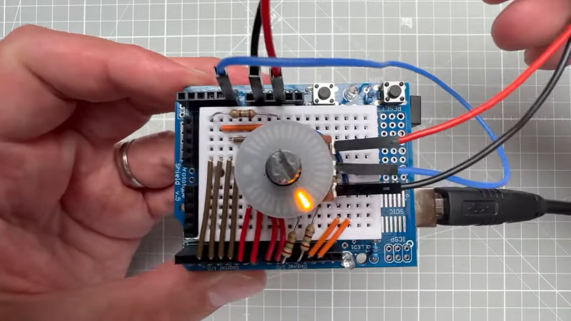
Sometimes, a hack isn’t really about the technology but about the logistics. If we asked you to light up an LED using an Arduino, there’s a good chance you’d know exactly how to do that. How about a bunch of LEDs? Simple. Now turn on LEDs proportional to an input voltage. A little harder, but nothing that you probably haven’t done a million times. Finally, arrange the LEDs in an attractive circle around a potentiometer. Wait, how are you going to do that? [Upir] shows us a ready-made ring light for just this purpose and you can see the beautiful thing in the video below.
We made the LED things sound slightly easier than it is. The ring light has 31 LEDs but only 12 pins, so there is some multiplexing going on. The modules come in pairs for about $20, so not a throwaway part, but they will really dress up anything that needs a knob of any kind.
Naturally, it doesn’t matter what you use to drive the LEDs. You could track a pot or a rotary encoder. Or you could show microphone levels or something else. After all, it is just a bunch of LEDs. For that matter, they’d probably make a good pair of robot eyes. Let us know what you want to use them for in the comments.
If your significant other is a little geeky, you might want a different kind of ring light. We couldn’t help but wish the LEDs on the ring were addressable. That would open up a world of interesting possibilities while reducing the pin count, too.


It looks really nice! But there’s an easier way to do it. 40-50 years ago, I had a stereo amp that did it. The knob had a clear plastic skirt, painted black on the back but with a varying-width slot in it. A similar variable-width slot was on the front panel. As the knob was rotated clockwise, the two slots aligned progressively more so that more light from the indicator lamp shown through.
You could also probably mount a let on the rotating contact part…
This. Far simpler and with much better (essentially infinite) resolution.
Even simpler, a plastic light pipe on the knob, lighted by a diffuser on the base board.
The adjustable mask design is definitely a simple, elegant hack if you always have the position of the knob to be able to control the aperture.
Where the circular LED bargraph is really helpful is when you have to use something like a quadrature encoder. The biggest use-case scenario is when the function of this knob is software-defined, and/or must be adjustable from multiple locations (e.g. a remote control panel). Putting the LEDs around the knob gives you direct visual feedback.
I had to dig a bit to find them, but here’s a link to ebay ($18 for 3):
https://www.ebay.com/itm/155586782272?hash=item2439b1e440:g:2nAAAOSwyjBW2RYA
Also, here’s a similar project with individual LEDs on a PCB in a circle to compare (that has the addressable LEDs):
http://midibox.org/forums/topic/21095-lre-4×1-breakable-rgb-led-ringrotary-encoder-pcb-bulk-order/
https://youtu.be/9XLm78iMxNs?si=DRM9gWXtUvNStE2P
Thanks
Thanks! I like that pricing a lot better. Too bad they aren’t red LED; that could look amazing for an understated simple car stereo in something like an 80s sports car.
I try to post this kind of link on YouTube, but the spam filters are erasing my posts and flagging me as spam. Even if I just mention generically what the street price is of something. Very hostile. Even on channels not selling anything: IE they have a post on X79 or X99 Xeons and I mention you can get LGA 2066 Xeons like W-2135 for $25, gets erased
A casual search on ali shows anything LGA 2066 in a completely different price league than X99 and especially X79. Just the MB’s are $00s whereas a complete X99 set (mb, cpu, ram) can be just $100.
I’ve heard of The Scarlet Pimpernel, but this the first time I’ve heard of Pimp the Potentiometer.
Now, who could have done it with a 555?
B^)
Interesting. Reminds me a bit of channel selector knobs of 1960s/1970s CB radios!
Also watched the video. My only complaint is the narrative. It’s very robotic and difficult to follow. A bit more practicing will make it sound more fluent. Especially pronunciation/emphasis. And I’m saying this as a non-native English speaker. ;)
The first part of this is a pretty good discussion of multiplexing and a fun idea for the display (VU meter? Suggested Setting? Max level?)
As far as the practicality/optimality of the display/Arduino/knob arrangement…the website isn’t PracticalADay is it?
Interesting, but at $10+ apiece, single color, when can I do a hack to use a circular OLED? Have the knob mounted to Lexan and then a gear drive to connect the Potentiometer. Would get many options, and visualizations would be pretty cool (I mean as long as we are hacking, go crazy). I’m now wondering if we could use a belt drive in the unused portion of travel and have internal bearings on the knob mounted to the clear sheet.
Or, and here it gets weird, encase the OLED into the knob, and perform a rotation on the video feed so it appears stationary. Use a clockspring connection like an automotive steering wheel does for the airbag and buttons.
(I only mention because the 1.28″ round LCD are $3 apiece, really beating the LED for price)
It would be simpler to make the “knob” from two concentric cylinders. The inner cylinder is fixed and mounts the display, while the outer cylinder does the actual rotating.
However, the utility is a question, as the normal posture for grasping and rotating a knob obscures the center of the knob with the palm of the hand.
You can buy assemblies like this, for example if you go on aliexpress and search for “2.1 inch 480*480 Round circular IPS color LCD display and magnetic encoder knob” they have a pretty high res screen with a encoder ring around the outside. I’m sure you could make it cheaper but it’ll give you an idea of how to make it or use it.
but does it go to 11?
Could be a good application for an LM3914.
It looks beautiful…. but $20 is a lot, and that doesn’t include the cost of an encoder that won’t break in a year.
I’d rather just build a fully digital UI with some Cherry MX clone switches, but it sure does look nice.
Their price will eventually drop; it’s just like every novelty that attempts to feed from early adopters, but will be surpassed very soon by RGB rings allowing for example to show multiple positions (think about average/peak signals, coaxial pots, old-new value, units/tens/hundreds etc: plenty of applications). They are cheap and not that hard to DIY: a 100 pack of SK6812 (smd 2020 RGB addressable LED) costs a few bucks ($5-7); add a very simple pcb and you’re done. They require a single gpio line to be used, therefore the simplest and cheapest uC out there will do.