Pimp The Potentiometer

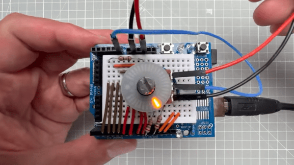
Sometimes, a hack isn’t really about the technology but about the logistics. If we asked you to light up an LED using an Arduino, there’s a good chance you’d know exactly how to do that. How about a bunch of LEDs? Simple. Now turn on LEDs proportional to an input voltage. A little harder, but nothing that you probably haven’t done a million times. Finally, arrange the LEDs in an attractive circle around a potentiometer. Wait, how are you going to do that? [Upir] shows us a ready-made ring light for just this purpose and you can see the beautiful thing in the video below.

We made the LED things sound slightly easier than it is. The ring light has 31 LEDs but only 12 pins, so there is some multiplexing going on. The modules come in pairs for about $20, so not a throwaway part, but they will really dress up anything that needs a knob of any kind.

Naturally, it doesn’t matter what you use to drive the LEDs. You could track a pot or a rotary encoder. Or you could show microphone levels or something else. After all, it is just a bunch of LEDs. For that matter, they’d probably make a good pair of robot eyes. Let us know what you want to use them for in the comments.

If your significant other is a little geeky, you might want a different kind of ring light. We couldn’t help but wish the LEDs on the ring were addressable. That would open up a world of interesting possibilities while reducing the pin count, too.

Continue reading “Pimp The Potentiometer”

Illustrated Kristina with an IBM Model M keyboard floating between her hands.

Keebin’ With Kristina: The One With The Foot Keyboard

[crispernaki]’s opening comments to this VCR head scroll wheel project lament that overall technical details aren’t “complex, ground-breaking, or even exciting.” Since when does that matter? The point is that not only did the thing finally, eventually get built, it gets daily use and it sparks joy in its owner.

This feel-good story is one of procrastination, laziness, and one aha! moment, and it’s roughly twelve years in the making. Inspired by an Instructable from long ago, [crispernaki] ran straight to the thrift store to get a VCR and take it apart.

The original plan was to just reuse the VCR head’s PCB and hide it in an enclosure, and then figure out way to block and unblock the path between an IR emitter/receiver pair. After many disemboweled mice and fruitless attempt, the project was once again shelved.

But then, [crispernaki] remembered the magnetic rotary encoder demo board that was just sitting around, along with various microcontrollers and Altoids tins. And it all quickly came together with a Teensy 2.0 and some bits and bobs, including a magnet glued on the shaft of the VCR head. A chip on the demo board does all the heavy lifting, and of course, the Teensy does the work of emulating an HID.

Continue reading “Keebin’ With Kristina: The One With The Foot Keyboard”

Hobnobbing With The Knob

The scroll wheel might be the best thing that happened to the computer mouse since, well, the computer mouse. But sometimes you want something a little more tangible. For example, with a software-defined radio setup, it doesn’t feel right to scroll your mouse to change frequencies. That’s where [Wagiminator]’ USB knob would come in handy. Marrying a 3D printed case, some addressable LEDs, a rotary encoder, and a CH552E microcontroller, the knob appears to the host operating system as a normal USB keyboard. That means most programs can use it without any special drivers or software.

There’s honestly not much to the hardware. A custom PCB holds two WS2812’s, the tiny CPU, the encoder, and the USB plug. There are a few random discrete components, too, but not many. Everything you need is on the project page. The PCB layout, the software, the schematics, and the 3D print files. The code that does the main work is extremely simple. The USB code is a bit more complex (look in the include directory) but honestly, it isn’t as bad as most USB examples we’ve seen.

This project is ripe for hacking. The software is simple enough to modify easily. The 3D printed case wouldn’t be hard to spruce up or print in different colors. Following the example, this would make a reasonable core for a custom keyboard peripheral that used exotic keys instead of a rotary encoder.

Knobs can be simple or complex. If you want our take on the odd volume control, we used sonar.

Make Your Own Pot And Encoder Knobs, Without Reinventing Them

Rotary potentiometers, switches, and encoders all share a basic design: adjustment is done via a shaft onto which a knob is attached, and knobs are sold separately. That doesn’t mean one knob fits all; there are actually a few different standards. But just because knobs are inexpensive and easily obtained doesn’t mean it’s not worth making your own.

A simple and effective indicator can be easily printed in a contrasting color.

Why bother 3D printing your own knobs instead of buying them? For one thing, making them means one can rest assured that every knob matches aesthetically. The ability to add custom or nonstandard markings are another bonus. Finally, there’s no need to re-invent the wheel, because [Tommy]’s guide to making your own knobs has it all figured out, with the OpenSCAD script to match.

By default, [Tommy]’s script will generate a knob with three shims (for interfacing to a splined shaft) when pot_knob(); is called. The number of shims can be adjusted by modifying potKnobDefaultShimCount. To give the knob a flat side (to interface with D-shafts), change flatted = false to flatted = true. And for adding a screw insert suitable for a set screw? Change tightenerDiameter = 0 from zero to the diameter desired.

The script is quite comprehensive and has sensible defaults, but it does require a bit of knowledge about OpenSCAD itself to use effectively. We have covered the basics of OpenSCAD in the past, and if you’re ready for a resource that will help you truly master it, here’s where to look.

Custom Printed Knobs In Just A Few Lines Of Code

While not everyone is necessarily onboard for the CAD-via-code principle behind OpenSCAD, there’s no denying the software lends itself particularly well to parametric designs. Using a few choice variables, it’s possible to make a model in OpenSCAD that can be easily tweaked by other users — even if they have zero prior experience with CAD.

Take for example this parametric-knob-maker written by [aminGhafoory]. The code clocks in at less than 100 lines, but if you’re looking to spin up your own version, all you really need to pay attention to are the clearly labeled variables up at the top. Just plug in your desired diameter and height, fiddle around a bit with the values that get fed into the grip generating function, and hit F7 to export it to an STL ready for printing.

Now admittedly, all the knobs generated with this code will look more or less the same. But that’s the beauty of open source, should you want to print out some wild looking knobs, you can at least use this code as a basis to build on. With the core functionality in place, you just need to concern yourself with writing a new function to generate a grip texture more to your liking.

Of course, if you want to make your OpenSCAD designs even easier for others to modify, you’ll want to look into its impressive customizer capability which replaces manually edited variables with friendly sliders and text input boxes. Projects like the Ultimate Box Maker we looked at back in 2018 are an excellent example of how powerful OpenSCAD can be if you give your design the proper forethought.

Odd Inputs And Peculiar Peripherals: RoenDi Smart Knob Thinks Outside The Box

When it comes to design decisions, we’re often advised to “think outside the box.” It’s generally good advice, if a bit abstract — it could really mean anything. But it appears that someone took it quite literally with this nifty little smart knob display and input device.

[Dimitar]’s inspiration for RoenDi — for “rotary encoder and display” — came from an unusual source: a car dashboard, and specifically, the multipurpose knobs that often crop up in a car’s climate control cluster. Designed for ease of use while driving while causing as little distraction as possible, such knobs often combine a rotary encoder with one or more indicators or buttons. RoenDi builds on that theme by putting a 1.7″ round LCD display in the middle of a ring attached to an Alps rotary encoder, allowing the knob to be customized for whatever you want it to represent. The backplane sports a powerful STM32 microcontroller with a lot of the GPIO pins broken out, so customization and interfacing are limited only by your imagination. The design is open source, so you can either build your own or support the project via Crowd Supply.

Unlike the haptic smart knob we’ve been seeing a bit about lately, which also features a round LCD at its center, RoenDi’s feedback is via the physical detents on the encoder. We think both devices are great, and they fill different niches in the novel input ecosystem.

Continue reading “Odd Inputs And Peculiar Peripherals: RoenDi Smart Knob Thinks Outside The Box”

An In-Depth Look At The Haptic Smart Knob

At Hackaday, we love those times when we get a chance to follow up on a project that we’ve already featured. Generally, it’s because the project has advanced in some significant way, which is always great to see. Sometimes, though, new details on the original project are available, and that’s where we find ourselves with [Scott Bez] and his haptic smart knob project.

Alert readers may recall [Scott]’s announcement of this project back in March. It made quite a splash, with favorable comments and a general “Why didn’t I think of that?” vibe. And with good reason; the build quality is excellent, and the idea is simple yet powerful. By attaching a knob to the shaft of a brushless DC motor and mounting a small circular LCD screen in the middle, [Scott] came up with an input device that could be reprogrammed on the fly. The BLDC can provide virtual detents at any interval while generating haptic feedback for button pushes, and the LCD screen can provide user feedback.

But how is such a thing built? That’s the subject of the current video, which has a ton of neat design details and build insights. The big challenge for [Scott] was supporting the LCD screen in the middle of the knob while still allowing the knob — and the motor — to rotate. Part of the solution was, sadly, a hollow-shaft motor that was out of stock soon after he released this project; hopefully a suitable replacement will be available soon. Another neat feature is the way [Scott] built tiny strain gauges into the PCB itself, which pick up the knob presses that act as an input button. We also found the way button press haptics are provided by a quick jerk of the motor shaft very clever.

This is one of those projects that seems like a solution waiting for a problem, and something that you’d build just for the coolness factor. Hats off to [Scott] for following up a sweet build with equally juicy details.

Continue reading “An In-Depth Look At The Haptic Smart Knob”