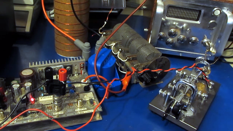
In the “don’t try this at home” category, [Joe Smith] builds a spark gap transmitter with a twist. The twist is that the drive power is from a signal generator attached to a FET. From there, though, things go classic using an automotive ignition coil and a tank circuit. He shows how adjusting the spark frequency changes the signal’s sound in a standard receiver.
We say don’t try this at home because the output of a transmitter like this will likely spew RF all over the place. Granted, there’s probably not much power, but it may well irritate your neighbors.
Switching to AM, you can really hear the tone from the spark frequency in the receiver. [Joe] posted some earlier videos where he made a 160-meter spark gap transmitter using an electric fly swatter. There are more details about how the tank circuits work in those videos. You can also see what the output looks like on a spectrum analyzer. You can hear what that transmitter sounds like, too.


1-8-4-3-6-5-7-2
V8 Firing order?
Small block Chevy firing order.
(Maybe others?)
The Mercedes M117 V8 uses that as well.
That ignition coil is from a GM V6
Spark gap transmitters have been illegal by international law since 1934.
Says who, the fun police? I don’t care.
Yes, because the only possible reason to regulate something like that is to infringe on people having “fun”. Not to keep radio useful for everyone. Not like this is literally just a broad-spectrum jamming device or anything lol. Nah, they just wanted to ban noisy transmitters specifically to be jerks.
I believe the rules merely say you can’t use the damped-wave emission type, not that you can’t use a spark gap.
A “continuous wave” isn’t actually continuous since it starts and stops, and turning on instantly would consume unnecessary bandwidth to either side of the CW frequency in the form of key clicks. So there’s a soft rise and fall time, and that’s quite like being damped but is entirely fine and effectively required. If you were to have zero rise or fall time, you would emit power all over the spectrum, including outside your own band, and you’d break the rules much more directly. A radio may choose a curve to use to soften any keying, and a duration for the curve that may be 5 milliseconds for normal rate or more if you slow down. That’s a lot of cycles of damping, but isn’t considered damped-wave.
With sufficient work, passing all other applicable criteria, it may be possible to make what’s technically a spark gap but is no longer really reasonable to consider as being damped in the way it was originally meant – you’ll be doing nothing that modern systems don’t do, except that you will consume your bandwidth all the time instead of just at the beginning and end of a dit or dah. Actually, your signal would probably look like someone who’s mimicing CW using an AM radio and a fixed tone, assuming you did make a *good* spark gap with a high enough Q and high rate of firing. Quenched or rotary, with attention paid to the details? Or just really really good filtering. I suppose an arc converter counts, and tesla coils are in that realm.
I suspect that that rig puts out enough spurious emissions for the FCC to come visiting.
Where is the rotary spark gap and its motor?
It is surprising how little spewed RF it takes to breach FCC Part 15 or CISPR. Agreed that Friendly Candy Company or an ARRL OO would come calling.
This article had me shaking my head. This (talented) person built a spark gap, and I’m reworking a DX-20 to have regulated B+ and screen voltages on the 6CL6. The 6CL6/6AG7 design was the best of designs from the ’50s to reduce chirp. I’m worried about chirp, which is minimal compared to a Spark’s spatter.
The ARRL Offical Observer program has been disbanded and replaced by the Volunteer Moniter Program run by Riley Hollingsworth K4DH de HR1/k2LCT
-1 for breaking the rules but +1 for using a bug key to do it. We just had a bug night through a local club and it was fun to hear all the fists singing.
I’ll call it a push.
On the one hand I don’t like things that create unnecessary interference and certainly not when it’s doing so beyond the law. So I get the complaints.
OTOH I also think the FCC has failed (probably other country’s organizations too but I don’t know them). They have allowed cheap electronics, especially cheaply made lighting to emit all sorts of interference and be mass marketed anyway.
At least this interference comes from a hobbyist actually building and learning something as opposed to just yet another tech-clueless cheapskate flicking a light switch.
The FCC does actively enforce the interference rules, but they have to get a complaint to know where there are problems.
“[Joe] posted some earlier videos where he made a 160-meter spark gap transmitter using an electric fly swatter.”
Don’t get many electric flies around here. 🤭