Raspberry Pi Changes HATs

Following on the heels of their Raspberry Pi 5 launch and some specifications for their RP1 all-in-one peripheral chip, the Raspberry Pi folks have now released an update to the HAT peripheral hardware specification reflecting the new model. Called the HAT+, it represents a major step forward with some significant changes.

Most visible will be changes to the mechanical specification, for while the original HAT specification was very rigid this new version is much looser. A HAT+ must only mate with the 40-pin connector, including the ID pins, and line up with only a single mounting hole compared to the four on the original. Electrically, a HAT+ must recognise the standby power state in which the 3.3-volt line is powered down while the 5-volt line remains active, while software-wise, there are changes to the content of the ID EEPROM including the ability to inform about stackable smaller HATs.

Continue reading “Raspberry Pi Changes HATs”

Terminal-Based Image Viewer, and Multi-OS Binary, and Under 100kb

[Justine Tunney]’s printimage.com is a program capable of splatting full-color images to text mode terminal sessions, but that’s not even its neatest trick. It’s also a small binary executable capable of running on six different operating systems: Linux, Windows, MacOS, FreeBSD, OpenBSD, and NetBSD. All without having to be installed or otherwise compiled first. On top of it all, it’s less than 100 kb.

How is this possible? It’s thanks to [Justine]’s αcτµαlly pδrταblε εxεcµταblε format, implemented by a project called Cosmopolitan which aims to turn C into a build-once-run-anywhere language. The printimage.com source code is included within the Cosmopolitan project.

If the name sounds a bit familiar, it’s probably because the Cosmopolitan project is a key piece of a tool we recently covered: llamafile, which allows people to package up an LLM (large language model) as a single-file, multi-OS executable.

As printimage.com shows, terminal windows are capable of more than just text. Still, plain ASCII has its appeal. Check out the ASCII art STL file viewer which might just make your next sick ASCII art banner a bit easier to generate.

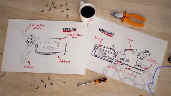
Two pieces of paper on a table with a pair of pliers, a screwdriver, and a cup of what is probably coffee or tea. The sheets show a diagram of a bicycle handlebar on one side with a labeled "controller box, controller lever, mount, and battery." The other sheet shows a side view of a 150kg servo mounted on a plate that runs over to a brake caliper with a battery, receiver, and power stabilizer. These parts are also labeled in red text.

Wireless Bike Brakes

Bicycles are the most efficient machines for moving a person around, and wireless drivetrains have been heralded as a way to make shifting more consistent and require less maintenance. [Blake Samson] wondered if the same could be true of wireless brakes.

A closeup of a bike front fork with a large 150kg servo mounted to a plate that puts it above the disc brake caliper. To the side of the caliper, wires are visible going between the servo, control box, and battery.Inspired by the controller for an RC car, [Blake] picked a 150 kg servo attached to a cable-actuated hydraulic disc caliper to apply the braking force. The servo, receiver, power stabilizer, and batteries were all mounted on a custom steel plate fabricated to mount under the caliper. [Blake] cut up an old set of mountain bike brake levers to reuse the handlebar mounts and then put the batteries, controller, and finger triggers on them.
Confident in his hacking skills, [Blake] then took the bike out on some trails to test the brakes. As a prototype, there were a few surprises along the way, like one of the triggers staying locked in the braking position, but they performed admirably enough that he’s mulling over a Mk. 2.

Bikes are one of our favorite hacking platforms. Be sure to checkout this dreamy cargo bike build, an awesome bike camper, or what can happen if your bike is dependent on the cloud to work.

Continue reading “Wireless Bike Brakes”

Make Carbon Fiber Tubes With An Open Source Filament Winder

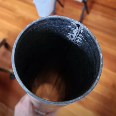
Result of winding a carbon fiber tube. (Credit: Andrew Reilley)

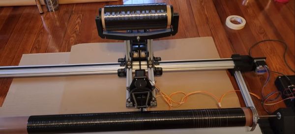
Carbon fiber (CF) is an amazing material that provides a lot of strength for very little weight, making it very useful for a lot of applications, ranging from rods in CoreXY 3D printers to model- and full-sized rockets. The model rocketry hobby is the reason why [Andrew Reilley] developed his own CF tube winding machine called Contraption. A tutorial video (also embedded below) shows how this machine is prepped for a winding run, followed by the winding progress and finalizing before admiring the result.

The entire machine’s design with 3D printed parts and off-the-shelf components is open source, as is the TypeScript and NodeJS-based Cyclone software that creates the toolpath specifying the parameters of the tube, including number of layers and the tow angle.

As a wet winding tow machine, the carbon fiber strands are led through the liquid resin before being wound onto the prepared mandrel. During winding some excess resin may have to be removed, and after the winding has been finished the tube is wound with shrink tape. This is followed by a heat gun session to shrink the tape and letting the resin cure. Following curing, the tape and mandrel are removed, resulting in a rather fancy looking CF tube that can find a loving home in a lot of applications, except perhaps ones that involving crushing outside pressures like those found deep below the ocean surface.

Continue reading “Make Carbon Fiber Tubes With An Open Source Filament Winder”

Bunnie Huang’s Shenzhen Guide Gets A New Edition – Written By Naomi Wu

If there’s one city which can truly claim to be the powerhouse of high-tech manufacturing here in the 21st century, it’s the Chinese city of Shenzhen. It’s likely that few people don’t own something made in that city or with parts that have passed through companies in the legendary electronic component markets of its Huaqiangbei district.

For years now the essential introduction to this world has come in the form of [Bunnie Huang]’s Essential Guide to Electronics in Shenzhen, a publication that unlocks the Chinese-speaking maze of vendors. All paper publications eventually become dated though, and this guide is no exception, so we’re very pleased to see a new version is on its way. Better still, it comes courtesy of Shenzhen native and maker extraordinaire [Naomi Wu], whose video series on YouTube has opened up so many corners of her city for those of us thousands of miles away. We can’t wait to see what she puts in it.

It’s also very good indeed on another level to see [Naomi]’s involvement, as earlier in the year she had to curtail her social media output under pressure from the Chinese government. We miss her unique window into the wonders of her city, and aside from her online shop it’s been concerning to hear very little from her of late. You can hear her talking about the book in a promotional video below the break.

Continue reading “Bunnie Huang’s Shenzhen Guide Gets A New Edition – Written By Naomi Wu”

Tech In Plain Sight: Super Glue

Many inventions happen not by design but through failure. They don’t happen through the failure directly, but because someone was paying attention and remembered the how and why of the failure, and learns from this. One of these inventions is Super Glue, the adhesive that every tinkerer and engineer has to hand to stick pretty much anything to anything, quickly. Although it was a complete failure for the original uses it was developed for, a chemist with good memory and an eye for a helpful product created it in a process he described as “one day of synchronicity and ten years of hard work.”

Super Glue was initially invented in 1942, when the chemist Harry Coover was working on a team trying to develop a clear plastic gun sight that would be cheaper than the metal ones already in use. The team cast a wide net, trying a range of new materials. Coover was testing a class of chemicals called cyanoacrylates. They had some promise, but they had one problem: they stuck to pretty much everything. Every time that Coover tried to use the material to cast a gun sight, it stuck to the container and was really hard to remove. 

When the samples he tried came into contact with water, even water vapor in the air, they immediately formed an incredibly resilient bond with most materials. That made them lousy manufacturing materials, so he put the cyanoacrylates aside when the contract was canceled. His employer B. F. Goodrich, patented the process of making cyanoacrylates in 1947, but didn’t note any particular uses for the materials: they were simply a curiosity. 

It wasn’t until 1951 when Coover, now at Eastman Kodak, remembered the sticky properties of cyanoacrylates. He and his colleague Fred Joyner were working on making heat-resistant canopies for the new generation of jet fighters, and they considered using these sticky chemicals as adhesives in the manufacturing process. According to Coover, he told Joyner about the materials and asked him to measure the refractive index to see if they might be suitable for use. He warned him to be careful, as the material would probably stick in the refractometer and damage it. Joyner tested the material and found it wasn’t suitable for a canopy but then went around the lab using it to stick things together. The two realized it could make an excellent adhesive for home and engineering use. Continue reading “Tech In Plain Sight: Super Glue”

Modern Spark Gap Transmitter Uses A Rotary Gap

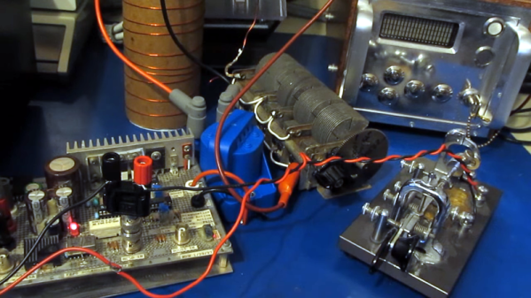
In the “don’t try this at home” category, [Joe Smith] builds a spark gap transmitter with a twist. The twist is that the drive power is from a signal generator attached to a FET. From there, though, things go classic using an automotive ignition coil and a tank circuit. He shows how adjusting the spark frequency changes the signal’s sound in a standard receiver.

We say don’t try this at home because the output of a transmitter like this will likely spew RF all over the place. Granted, there’s probably not much power, but it may well irritate your neighbors.

Switching to AM, you can really hear the tone from the spark frequency in the receiver. [Joe] posted some earlier videos where he made a 160-meter spark gap transmitter using an electric fly swatter. There are more details about how the tank circuits work in those videos. You can also see what the output looks like on a spectrum analyzer. You can hear what that transmitter sounds like, too.

Continue reading “Modern Spark Gap Transmitter Uses A Rotary Gap”